Anritsu MS271xE series of handheld spectrum analyzers up to 6 GHz
Brief description of the series
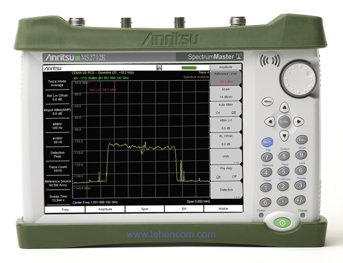
Anritsu MS2712E and MS2713E are two portable spectrum analyzers from the American company Anritsu with excellent performance and a wide range of useful functions. The MS2712E operates from 9 kHz to 4 GHz and the MS2713E operates from 9 kHz to 6 GHz. At the same time, both models of spectrum analyzers have a resolution (RBW) from 1 Hz to 3 MHz in steps of 1-3. Also supported with the quasi-peak detector are 200 Hz, 9 kHz, 120 kHz bands for preliminary electromagnetic compatibility (EMC) testing.
The MS2712E and MS2713E analyzers are designed specifically to solve a variety of modern problems: from testing mobile networks at all stages of their operation (including demodulation and quality analysis of wireless communication standards LTE, TD-SCDMA/HSPA+, GSM/EDGE, W-CDMA/HSPA+, CDMA, EV-DO, Fixed and Mobile WiMAX, ISDB-T, DVB-T/H, as well as CPRI and OBSAI), to searching for radio jammers and even developing and testing RF devices. A full description of all the characteristics of these analyzers can be downloaded below on this page in the Documentation section.
All models of the series
The Anritsu MS271xE series consists of two models, which are presented in this interactive table. To see all the characteristics of certain models, add them to the comparison.
| Model |
Maximum frequency
|
Signal analysis bandwidth
|
RF signal generation
|
RF power measurement
|
Operating temperature
|
Weight
|
|---|---|---|---|---|---|---|
|
Promotion
MS2712E
Demo
|
4 GHz | 20 MHz | 500 kHz – 4 GHz | 10 MHz – 4 GHz | From -10°С to +55°С | 3.45 kg |
|
MS2713E
|
6 GHz | 20 MHz | 500 kHz – 6 GHz | 10 MHz – 6 GHz | From -10°С to +55°С | 3.45 kg |
Main features of the series
Frequency: 9 kHz - 4 GHz (model MS2712E).
Frequency: 9 kHz - 6 GHz (model MS2713E).
Resolution (RBW): 1 Hz - 3 MHz. Amplitude: +26 dBm to -162 dBm.
Built-in preamplifier (standard). Noise: -162 dBm.
Bandwidth (RBW) support 200 Hz, 9 kHz, 120 kHz with quasi-peak detector for preliminary EMC and EMI tests.
Standard measurements: spectrum and signal analysis, field strength, channel power, occupied bandwidth, adjacent channel power ratio (ACPR), carrier-to-interference ratio (C/I), AM/FM/SSB demodulation, etc.
Additional options: tracking generator (2-port frequency response analysis, etc.) (option 0020), channel scanner (option 0027), analysis of non-stationary signals and interference (option 0025), drawing coverage areas on a map (option 0431), supply of direct voltage to the central conductor (option 0010), built-in power meter (option 0029), high-precision power measurement with sensors (option 0019), GPS receiver (option 0031), external sweep trigger (option 0090), AM/FM/PM analyzer (option 0509), Ethernet connection port (option 0411), PIM level determination, etc.
Demodulation and quality analysis of wireless communication standards: GSM/EDGE, W-CDMA/HSPA+, LTE and TD-LTE, CDMA, EV-DO, Fixed and Mobile WiMAX, TD-SCDMA/HSPA+, ISDB-T, DVB-T/H, etc.
Convenient touch screen. User Interface Russified.
Interfaces: USB standard, Ethernet (option 0411).
Operating temperature range: from -10°С to +55°С. Weight: 3.45 kg. Dimensions: 27 cm x 20 cm x 9 cm.
Areas of use:
- cellular networks at all stages of operation;
- radio planning and radio monitoring;
- development and testing of microwave devices;
- search for radio bugs and jammers;
- preliminary EMC tests;
- demodulation and analysis of the quality of wireless communication standards: LTE, GSM / EDGE, W-CDMA / HSPA +, TD -SCDMA, CDMA, EV-DO, Fixed and Mobile WiMAX, ISDB-T, DVB-T/H, as well as CPRI and OBSAI.
Need more functionality? See Anritsu MS2720T series.
Need spectrum analyzer up to 54 GHz? See Anritsu MS2090A Field Master Pro series.
Need an analyzer cheaper? See Tektronix RSA306B model.
Need built-in antenna analyzer? See Anritsu S3xxE series.
You need a spectrum analyzer combined with an oscilloscope? See Tektronix MDO3000 series.
Want to see the full list? This page has everything to choose and buy a spectrum analyzer.
Universal analyzer for different tasks
Specialists working with mobile and wireless communication networks will be helped in their work by: small dimensions (27 cm x 20 cm x 9 cm) and weight of the analyzer (only 3.5 kg), wide temperature range (from -10°C to +55°C) and battery power, a built-in demodulator of all modern communication standards (with a 20 MHz band), which will help to optimally configure base stations of the mobile network. The following options will also help automate routine tasks: channel scanner (option 0027), an analyzer of non-stationary signals and interference with the possibility of direction finding and fixing the signal source on the map (option 0025), drawing coverage areas (radio signal strength) on a map or floor plan (option 0431), GPS receiver (option 0031), the possibility of supplying direct voltage to the central core to power active microwave devices (option 0010), tracking generator (option 0020), built-in power meter (option 0029) or high-precision power measurement with an external sensor (option 0019).

For those who do radio monitoring, as well as the search for radio bookmarks and similar devices help in your work: a built-in preamplifier (which provides the MS2712E and MS2713E analyzers with a noise level of up to -162 dBm), small dimensions and weight, a wide temperature range and battery power, an analyzer of non-stationary signals and interference with the possibility of direction finding and fixing the signal source on the map (option 0025), drawing coverage areas (radio signal strength) on a map or floor plan (option 0431), GPS receiver (option 0031), AM/FM/SSB demodulation (option 0509).
By purchasing an Anritsu MS2712E or MS2713E spectrum analyzer, developers of microwave devices will receive a portable and very convenient analyzer with the technical characteristics of an expensive laboratory instrument. Here are some of the impressive features that each MS2712E and MS2713E deliver: Noise Floor (with preamp on): up to -162dBm, Resolution (RBW): 1Hz - 3MHz, Input Amplitude: +26dBm to -162dBm , the frequency accuracy of the internal reference oscillator is 0.05 ppm (when GPS is on (option 0031)). Also in the development and testing of microwave devices can be used: tracking generator (option 0020), the possibility of supplying direct voltage to the central core to power active microwave devices (option 0010), built-in power meter (option 0029) or high-precision power measurement with an external sensor (option 0019), external sweep trigger (option 0090), Ethernet connection port (option 0411) to include the analyzer in hardware and software systems. All these features can be used both at the stage of development in the laboratory and at the stage of testing in real places where your devices are used: in any weather and any season!
It's no secret that laboratory spectrum analyzers for electromagnetic compatibility (EMC) testing are very expensive. Therefore, manufacturers of various equipment, as well as certification centers, use inexpensive portable analyzers Anritsu MS2712E and MS2713E, together with the corresponding set of antennas, for preliminary tests for EMC and EMI in the laboratory and in the field. To do this, the analyzers support bands (RBW) 200 Hz, 9 kHz, 120 kHz with a quasi-peak detector, as well as the ability to carry out measurements taking into account the real gains of your antenna (they can be easily written to the analyzer's memory using the included free software).
Spectrum and signal analyzers MS2712E and MS2713E are inexpensive, lightweight, compact and very reliable. Designed and manufactured in the USA. Before shipment to the customer, each copy of the device undergoes final quality control at the factory (tested in a heat chamber for 48 hours).
Great performance in a portable package
Spectrum and signal analyzers Anritsu MS2712E, MS2713E have excellent sensitivity and dynamic range, which allows you to work with very weak signals, as well as signals that are difficult to detect against another strong signal (for example, a nearby transmitter). The built-in preamplifier and the ability to set the resolution bandwidth (RBW) to 1 Hz also help in solving such problems.
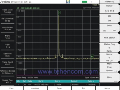
Dynamic range is 102 dB. |
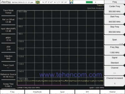
Typical noise floor is between -155 and -160 dBm. |
Automatic measurements
To automate work and speed up routine tasks, Anritsu MS2712E, MS2713E spectrum and signal analyzers allow you to automatically measure: field strength (taking into account the real gains of any antenna), channel power, occupied bandwidth (as a percentage of power or by a given level in dB), adjacent channel power ratio (ACPR), carrier power to interference ratio (C/I). It is also possible to carry out AM/FM/SSB demodulation with audio signal output to the built-in speaker or headphones.
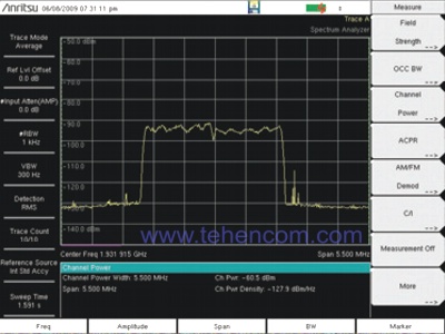
Automatic channel power measurement. |
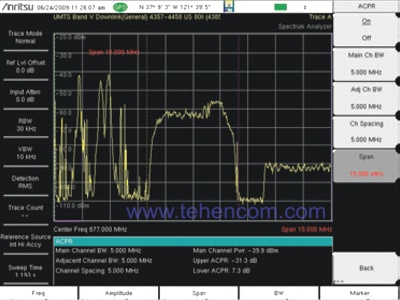
Automatic adjacent channel power factor measurement (ACPR). |
Ease of use
The convenience of working with the device directly affects the speed and quality of the tasks. Anritsu MS2712E, MS2713E spectrum analyzers support many useful and convenient functions: upper and lower limit lines (signal masks) with the ability to automatically save measurements when the signal goes beyond the specified limits, up to 6 markers, including 6 delta markers, as well as a marker table, the ability to measure the noise level in units of dBm/Hz or dBmkV/Hz
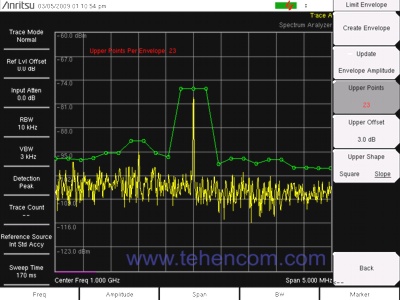
Upper limit line (signal mask) with the ability to automatically save the measurement |
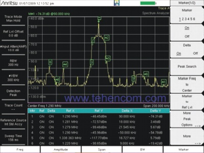
6 markers including 6 delta markers plus a marker table |
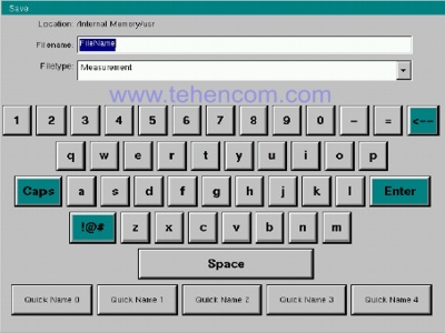
Since the screen of the MS2712E and MS2713E analyzers is touch-sensitive, the developers were able to implement an on-screen keyboard that allows entering the names of saved files and comments in a matter of seconds. This feature saves a lot of work time, which is usually spent entering filenames with separate buttons.
Bias-Tee (option 0010)
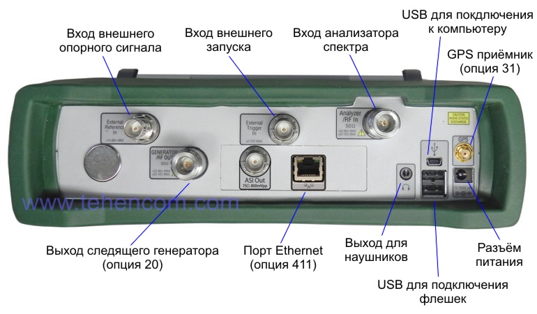
This hardware option adds the ability to supply DC voltage to the central contact of the microwave connector of Anritsu MS2712E, MS2713E spectrum analyzers to power active devices in the radio path (amplifiers, repeaters, etc.). The technical characteristics of this option are given below:
- modes: ON/OFF, voltage, current (low level 250 mA or high level 450 mA);
- voltage range: from +12 V to +32 V;
- output voltage setting resolution: 0.1 V.
Tracking Generator (option 0020)
This hardware option adds a complete tracking generator to the Anritsu MS2712E and MS2713E spectrum and signal analyzers with the following features:
- frequency range: 500 kHz – 4 GHz (for MS2712E), 500 kHz – 6 GHz (for MS2713E);
- output power range: from -50 dBm to 0 dBm;
- output power resolution: 0.1 dB;
- output power unevenness: no more than 1 dB (typical value 0.3 dB);
- possibility of generating a continuous signal at a fixed frequency: yes.
The tracking generator is excellent for measuring the frequency response of passive and active devices of the radio frequency path (cables, filters, attenuators, amplifiers, repeaters). Also, using a tracking generator, you can measure the level of isolation (coupling) between antennas. And the dynamic range of more than 80 dB and the powerful capabilities of the MS2712E and MS2713E for mathematical processing of signal traces allow you to effectively measure the parameters of duplexers (frequency separation filters) and other similar devices.
Option 0010 is provided to power active radio path devices connected to the input of the spectrum analyzer. With this option, a DC voltage (12 to 32 V) can be applied to the central pin of the analyzer's microwave connector.
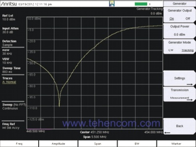
Example of measurements made with a tracking generator |
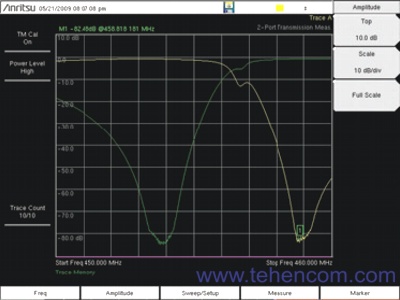
Measurement of parameters of duplexers |
This video shows the features of the built-in tracking generator (option 0020) that can be fitted to the Anritsu MS2712E and MS2713E handheld spectrum analyzers. As an example, a bandpass filter measurement is shown.
Measuring power with precision sensors (option 0019)
This software option, implemented in the Anritsu MS2712E, MS2713E spectrum analyzers, adds the ability to accurately measure the microwave power of modulated and unmodulated signals using external sensors that are connected to the analyzer's USB port. To work with this option, you need one of the sensors: PSN50 (the cheapest), MA24105A (power throughput up to 150 W), MA24106A, MA24108A, MA24118A or MA24126A.
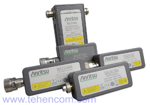
The frequency range, measurement accuracy and type of measured power (average, peak, absorbed or transmitted) depend on the sensor model. The accuracy of these sensors averages 0.16 dB (about 3%). You can find detailed information about sensors in the section of our website: Microwave wattmeters, voltmeters and microwave power sensors, a summary is given below.
Standard sensors with 100 Hz video bandwidth:
- RMS sensor for microwave power Anritsu PSN50 (50 MHz – 6 GHz, -30 dBm to +20 dBm);
- USB pass-through peak microwave power sensor Anritsu MA24105A (350 MHz – 4 GHz, up to +52 dBm (150 W));
- USB RMS microwave power sensor Anritsu MA24106A (50 MHz – 6 GHz, -40 dBm to +23 dBm).
Fast sensors with 50 kHz video bandwidth:
- USB RMS microwave power sensor Anritsu MA24108A (10 MHz – 8 GHz, -40 dBm to +20 dBm);
- USB RMS microwave power sensor Anritsu MA24118A (10 MHz – 18 GHz, -40 dBm to +20 dBm);
- USB RMS microwave power sensor Anritsu MA24126A (10 MHz – 26 GHz, -40 dBm to +20 dBm).
In addition, when measuring high levels of microwave power, you may need attenuators, which can be selected in the section of our website: microwave accessories. If there are unwanted frequency components in the input signal, they can be suppressed with narrow-band filters, which can also be selected in the section of our website: microwave accessories. For a less accurate power measurement without the use of external sensors, you can use option 0029.
A detailed description of this option can be found on this page in the section Documentation.
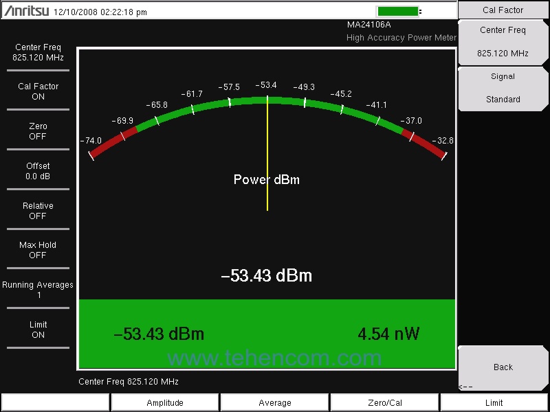
Built-in power meter (option 0029)
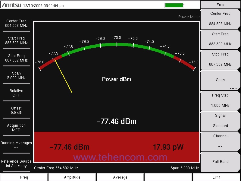
This software option, implemented in the Anritsu MS2712E, MS2713E spectrum analyzers, adds the ability to measure microwave power in a given frequency range and display the measurement result on the device screen in a convenient graphical form. The measurements performed by this option are based on the operation of a spectrum analyzer. It is also possible to measure the power of an individual channel of various mobile communication standards by selecting the type of communication standard (GSM, CDMA, LTE, WiMAX, etc.) and the channel number.
Specifications for option 0029:
- frequency range: 10 MHz – 4 GHz (for MS2712E), 10 MHz – 6 GHz (for MS2713E);
- input power range: -120 dBm to +26 dBm;
- power measurement error at frequency up to 4 GHz: 1.25 dB or less (0.5 dB typical);
- power measurement error above 4 GHz: 1.5 dB or less (0.5 dB typical).
For accurate measurement (0.16 dB error) of average, peak, absorbed or transmitted power up to 150 W, you can use external sensors in conjunction with option 0019.
In addition, when measuring high levels of microwave power, you may need attenuators, which can be selected in the section of our website: microwave accessories. If there are unwanted frequency components in the input signal, they can be suppressed with narrow-band filters, which can also be selected in the section of our website: microwave accessories.
A detailed description of this option can be found on this page in the section Documentation.
GPS receiver (option 0031)
This hardware option, implemented in the Anritsu MS2712E, MS2713E spectrum analyzers, adds a built-in GPS receiver that allows you to supplement the measurement results with the exact coordinates of the measurement location and the time when the measurement was performed. Also, when synchronized from GPS, the spectrum analyzer measures the frequency of signals 30 times more accurately (with an accuracy of 0.05 ppm compared to the standard 1.5 ppm), which is necessary in a number of applications, for example, when measuring LTE, EV-DO, CDMA, etc., as well as in the development of microwave devices.
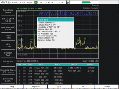
In the GPS information window, you can check the synchronization parameters with satellites. |

External view of the magnetic GPS antenna, which is part of option 0031. |
The built-in GPS receiver has another useful use: it is used to determine the location of the MS2712E and MS2713E when working with the transient and interference analyzer option (option 0025) and the option of drawing coverage areas on the map (option 0431).
A detailed description of this option can be found on this page in the section Documentation.
External sweep trigger (option 0090)
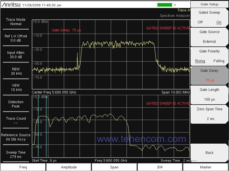
This software option allows you to trigger the sweep (start of measurement) from an external pulse applied to the External Trigger In input of the Anritsu MS2712E and MS2713E spectrum analyzers. In the options menu, you can set the trigger parameters: on the pulse edge, on the pulse decay, etc. The option is used mainly in the laboratory for synchronization of measurements, or when MS2712E, MS2713E are used as part of software and hardware systems.
A detailed description of this option can be found on this page in the section Documentation.
Search for signal and interference sources (option 0025)
This software option, implemented in the Anritsu MS2712E, MS2713E spectrum analyzers, adds a number of useful features: the frequency-time diagram mode (used to detect non-stationary signals and rare interference, as well as the instability of signal sources in frequency), the direction finder mode with the formation of an audio signal, the tone of which depends on the power of the radio signal, measurement of signal strength at a given frequency (RSSI), automatic detection of the type of signal (GSM, CDMA, etc.) on the spectrogram (Signal ID mode).
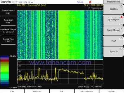
Time-frequency diagram mode (signal recording up to 3 days). |
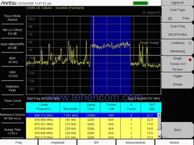
Automatic signal type detection (GSM, CDMA, etc.). |
Also, if available options 0031 (GPS), option 0025 allows you to perform direction finding of a radio signal source with plotting its location on a map directly on the device screen and then saving it to a file. A map of the area can be downloaded to the screen of the device using a free program Map Master, which is shipped with MS2712E and MS2713E. In addition, you can use any of your maps (in JPEG, TIFF, BMP, GIF and PNG formats), including scanned images, the main thing is to set the GPS coordinates of the two corners of the map.
A detailed description of this option can be found on this page in the section Documentation.
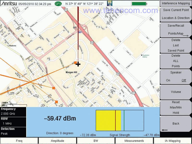
Drawing coverage areas on a map (option 0431)
This software option, implemented in the Anritsu MS2712E, MS2713E spectrum analyzers, allows you to plot the signal strength level at a given frequency (RSSI) or adjacent channel power ratio (ACPR) on a map or floor plan. The power level on the map is displayed in different colors (the higher the power, the more intense the shade of red used).
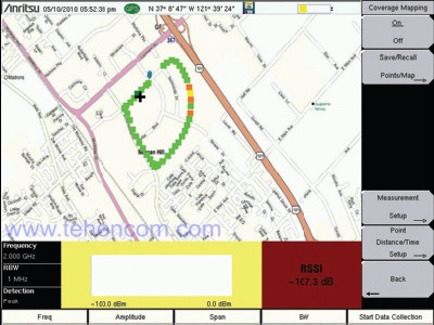
An example of plotting signal strength levels on a terrain map. |
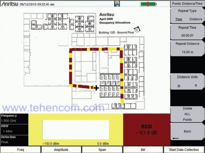
An example of applying signal strength levels to a floor plan. |
To work on the ground, you must have a GPS receiver (option 0031). It is not necessary to have a GPS receiver to work with floor plans. Maps and plans are created and loaded into the device using a simple and convenient program Map Master which is included in the package. Map Master can create maps using Google satellite imagery or by importing any JPEG, TIFF, BMP, GIF and PNG maps, including scanned images. For documentation and reporting, maps and floor plans with measurement results can be transferred to a computer as files in JPEG and KML formats.
A detailed description of this option can be found on this page in the section Documentation.
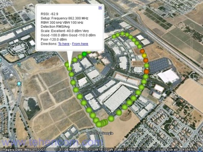
An example of applying signal strength levels to a satellite photograph of an area (Google satellite photos were used). |
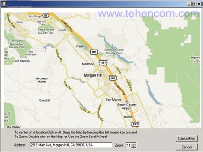
The window of the Map Master program, with the help of which any maps can be prepared and loaded onto the screen of the Anritsu MS2712E, MS2713E analyzers. |
Channel scanner (option 0027)
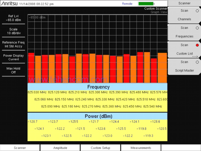
This software option, implemented in Anritsu MS2712E, MS2713E spectrum analyzers, is very popular with specialists working with mobile communication systems, as it allows you to automate the power measurement of individual channels of any communication standards (GSM, TDMA, CDMA, W-CDMA, HSDPA, WiMAX, LTE, public safety systems, etc.). You can display the measurement results in the form of power groups for each channel. One group can have from 1 to 20 channels. You can create up to 60 such groups in total. The start and end frequencies of each channel can be individually set by the user of the device or simply selected from a large list of existing communication standards.
A detailed description of this option can be found on this page in the section Documentation.
AM/FM/PM modulation analyzer (Option 0509)
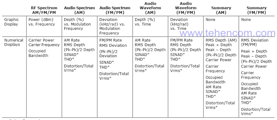
This software option implemented in spectrum analyzers Anritsu MS2712E, MS2713E is used to check the quality of amplitude, frequency and phase modulation (AM/FM/PM) of various radio transmitting stations.
Option 0509 has 4 modes:
1. RF spectrum display mode, including measurement of carrier power, carrier frequency, and occupied bandwidth.
2. Audio spectrum display mode including measurements: Rate, RMS (depth and deviation), Pk-Pk/2 (depth and deviation), SINAD, THD and Distortion/Total. The scale on the horizontal axis can be selected from the list: 2 kHz, 5 kHz, 10 kHz or 20 kHz.
3. Time domain audio display mode, including measurements: Rate, RMS (depth and deviation), Pk-Pk/2 (depth and deviation), SINAD, THD and Distortion/Total.
4. Mode of simultaneous display of all measurements in the form of a table (Summary).
A detailed description of this option can be found on this page in the section Documentation.
20 MHz signal demodulator (option 0009)
This hardware option adds a demodulator board with up to 20 MHz bandwidth to the Anritsu MS2712E and MS2713E spectrum and signal analyzers, allowing demodulation and analysis of all modern mobile and wireless data standards: GSM/EDGE, W-CDMA/HSPA+, LTE and TD -LTE, CDMA, EV-DO, Fixed and Mobile WiMAX, TD-SCDMA/HSPA+, ISDB-T, DVB-T/H, etc.
Option 0009 is required for software demodulation and analysis of the following standards:
- GSM/GPRS/EDGE (option 0880);
- W-CDMA/HSPA+ (option 0881);
- LTE/LTE-A FDD/TDD (option 0883);
- LTE 256QAM (option 0886);
- CDMA/EV-DO (option 0884);
- Fixed and Mobile WiMAX (option 0885);
- TD-SCDMA/HSPA+ (option 0882);
- ISDN-T (option 0030);
- ISDB-T (options 0032, 0079);
- SDVB-T/H (option 0078);
- DVB-T/H (options 0057, 0064);
- NB-IoT (options 0887);
- CPRI and OBSAI (options 0752, 0753, 0759).
The following are examples of how the Anritsu MS2712E and MS2713E analyzers operate in various demodulation and mobile standards analysis modes. A detailed description of these options can be found on this page in the section Documentation.
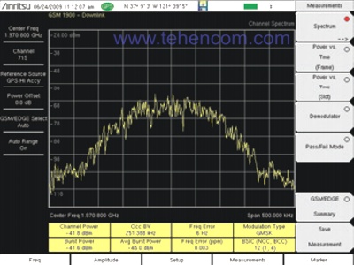
GSM Occupied Bandwidth Measurement: if the signal goes beyond the allowable limits, it can lead to a failure in the operation of adjacent channels and is an indicator of a failure in the operation of the base. |
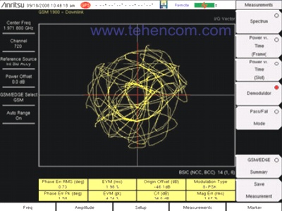
GSM demodulation and EVM measurement: The measurement of vector modulation error (EVM) is very important, because a bad EVM value leads to connection failure, low data rate, etc. |
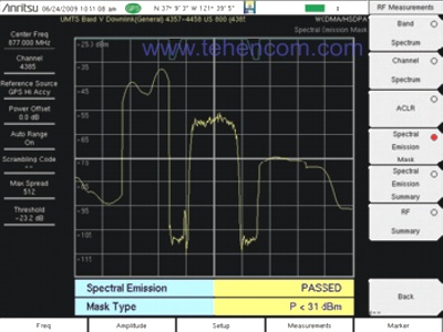
Spectral Density W-CDMA/HSPA+: |
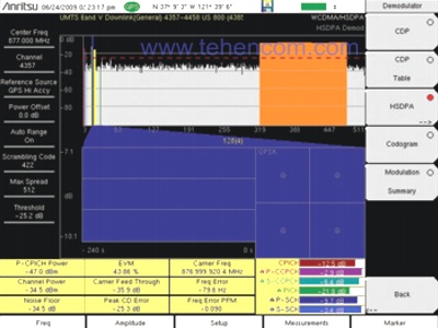
W-CDMA/HSPA+ demodulation and EVM measurement: Measurement of vector modulation error (EVM) is very important, because a bad EVM value leads to a broken connection, low data rate, low sector capacity and other failures. |
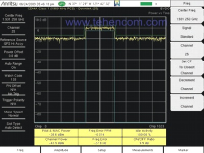
Pilot and MAC power measurement in EV-DO: high or low levels lead to synchronization errors, connection failure, inability to establish a connection, etc. |
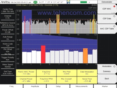
EV-DO demodulation: allows you to check the quality of signal transmission by 17 key parameters: frequency error, Rho Pilot, Rho Mac, Rho Data, etc. |
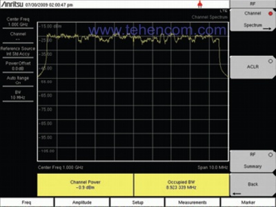
LTE Occupied Bandwidth Measurement: example of bandwidth measurement at 99% power; exceeding the occupied bandwidth leads to a parasitic effect on adjacent channels. |
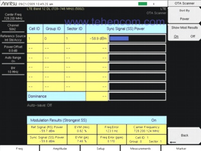
Measurement of LTE characteristics from the air: measurement of the power of the synchronization signal and individual subcarriers allows you to determine the cause of the low data rate. |

Constellation diagram of Mobile WiMAX: the diagram clearly shows what type of modulation is used, as well as the main parameters of the signal modulation quality (EVM, RCE, etc.). |
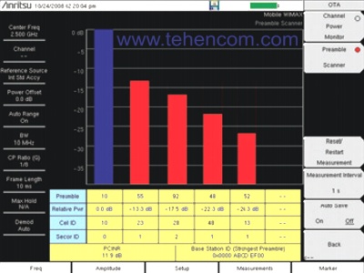
Measurement of WiMAX characteristics from the air: a low PCINR (carrier-to-noise ratio) indicates poor signal quality and low sector capacitance. |
Ethernet port (option 0411)
Each Anritsu MS2712E and MS2713E Spectrum and Signal Analyzer comes with this option free of charge, which is an RJ45 connector for connecting the instrument to an Ethernet network. Compared to a standard USB connection, an Ethernet connection is best suited for using devices as part of hardware and software systems, as it provides a high data transfer rate and a short device response time to control commands. DHCP dynamic IP address assignment mode is supported, as well as static IP address mode. Command sets are used to control the device, which are described in detail in Programming Guide, available in the section Documentation.
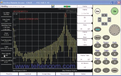
In addition to the ability to control the instrument over a network using a set of software commands, the Ethernet option can be used to remotely control the analyzer using a ready-made free program. Line Sweep Tools from Anritsu, which is included in the package. When using this program, the appearance of the device (with display and buttons) is completely repeated on the computer screen and it is possible to remotely control the analyzer using the mouse.
A detailed description of this option can be found on this page in the section Documentation.
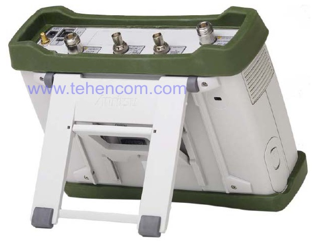
Portable, convenient design
Specifications of Anritsu MS271xE
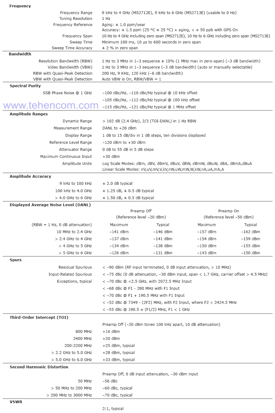
This figure lists the main technical specifications of the Anritsu MS271xE series analyzers. Detailed technical specifications occupy 36 pages in a PDF file and are located below on this page in the Documentation section.
Anritsu MS271xE package contents
| Name | Short description |
| Anritsu MS2712E | Handheld Spectrum and Signal Analyzer (9 kHz - 4 GHz) |
| or | |
| Anritsu MS2713E | Handheld Spectrum and Signal Analyzer (9 kHz - 6 GHz) |
| plus: | |
| 10920-00060 | CD with documentation |
| 2300-498 | Anritsu Master Software Tools (MST) DVD disc |
| 2300-530 | Anritsu Line Sweep Tools (LST) PC DVD |
| 2300-532 | CD-ROM with program for computer Map Master |
| 633-44 | Li-Ion battery |
| 40-168-R | Power Supply |
| 806-141-R | Car cigarette lighter charger |
| 3-2000-1498 | USB cable A - mini-B, 3 meters |
| 2000-1654-R | Soft carry bag |
| 11410-00511 | Specifications for Spectrum and Signal Analyzers MS2712E, MS2713E |
| 10580-00251 | English user manual |
| - | User's manual in Russian |
| - | Calibration certificate |
| - | 1 year warranty (can be extended to 3 and 5 years) |
Options and accessories for Anritsu MS271xE
Below is a list of software and hardware options for the Anritsu MS2712E and MS2713E spectrum and signal analyzers, which can be used to solve almost all measurement tasks. For a complete list of optional accessories, see documentation for MS2712E, MS2713E. In addition, you can choose auxiliary equipment from the following sections of our website: Measuring antennas and Microwave accessories.
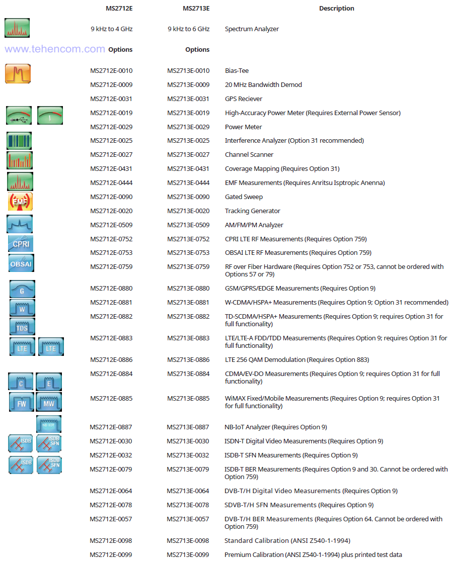
You can find detailed information about these options at the links:
- DC voltage supply to the central conductor - Bias-Tee (option 0010);
- tracking generator (option 0020);
- power measurement with precise sensors (option 0019);
- built-in power meter (option 0029);
- GPS receiver (option 0031);
- external sweep trigger (option 0090);
- an analyzer of non-stationary signals and interference with the possibility of direction finding and fixing the signal source on the map (option 0025);
- drawing coverage areas on the map (option 0431);
- channel scanner (option 0027);
- analyzer of modulation parameters AM/FM/FM (AM/FM/PM) (option 0509);
- hardware demodulator of signals with a bandwidth of up to 20 MHz (option 0009) for demodulation and analysis of wireless standards GSM/EDGE, W-CDMA/HSPA+, LTE and TD-LTE, CDMA, EV-DO, Fixed and Mobile WiMAX, TD-SCDMA/HSPA+, ISDB-T, DVB-T/H, as well as CPRI and OBSAI;
- Ethernet connection port (option 0411).
Documentation
This PDF documentation contains the most comprehensive description of Anritsu MS2712E and MS2713E Spectrum and Signal Analyzers features, specifications and modes of operation:
Description of portable analyzers Anritsu MS2712E and MS2713E (in English) (40 pages; 31 MB)
Anritsu MS2712E and MS2713E analyzer specifications (in English) (36 pages; 6 MB)
Anritsu MS2712E and MS2713E basic measurements and options description (in English) (296 pages; 22 MB)
LTE, W-CDMA, GSM and NB-IOT measurement guide (in English) (252 pages; 22 MB)
User manual Anritsu MS2712E and MS2713E (in English) (118 pages; 11 MB)
Anritsu MS2712E and MS2713E programming guide (in English) (540 pages; 5 MB)
And here you can find our tips and other useful information on this topic:
Brief information about the Anritsu MS2712E and MS2713E analyzers (in English) (2 pages; 4 MB)
User manual Anritsu MS2712E and MS2713E (in Russian) (74 pages; 2 MB)
A brief overview of all series of Anritsu RF measuring instruments
An overview of all series of Anritsu handheld RF analyzers
Anritsu handheld radio meter models and options
Basic theory for spectrum analysis and signal analysis
How to buy equipment cheaper – discounts, special prices, demo and used devices
To simplify the process of choosing a spectrum and signal analyzer, you can use our experience and recommendations. We have over 20 years of practical supply experience and can immediately answer many questions about models, options, delivery times, prices and discounts. This will save your time and money. For this it's simple call us or write to us at E-mail and we will be happy to answer your questions.


