40G, 100G, 200G and 400G network testing
Brief introduction
Data transfer speeds are constantly growing, and if quite recently links with a speed of 40G were considered exotic, now they are quite widespread around the world in data centers and in the backbone networks of mobile operators and Internet providers. But progress in this area does not stop and equipment for data transmission with speeds of 100G, 200G and 400G has already been standardized and produced.
A significant increase in speed required the development of new information transfer protocols (for example, IEEE 802.3bs, IEEE 802.3ba, OTU4), new types of optical signal modulation (NRZ-DP-QPSK), the introduction of mandatory error checking and correction (FEC) and many other technical innovations. .
All these novelties and improvements significantly complicate the procedure for building and launching such networks, as well as put forward increased requirements for personnel and measuring equipment necessary to maintain their performance during operation.
This page contains the main information from a detailed guide compiled by the company's specialists. EXFO, summarizing all the important information on the technologies of modern high-speed networks. Also in this manual are models of instruments for carrying out all types of measurements and describes the methods for their correct application. The full text of the manual can be downloaded in PDF format:
100G and 400G Network Test Guide (English) (138 pages; 18 MB)
Overview of technologies from 40G to 400G
The figure below shows the roadmap (according to the Ethernet Alliance) for increasing Ethernet speeds from 10 Mbps in the early eighties to 400 Gbps currently being implemented. Yellow circles indicate standardized speeds, gray circles indicate speeds currently being tested in pilot projects (800 Gbps and 1.6 Tbps).
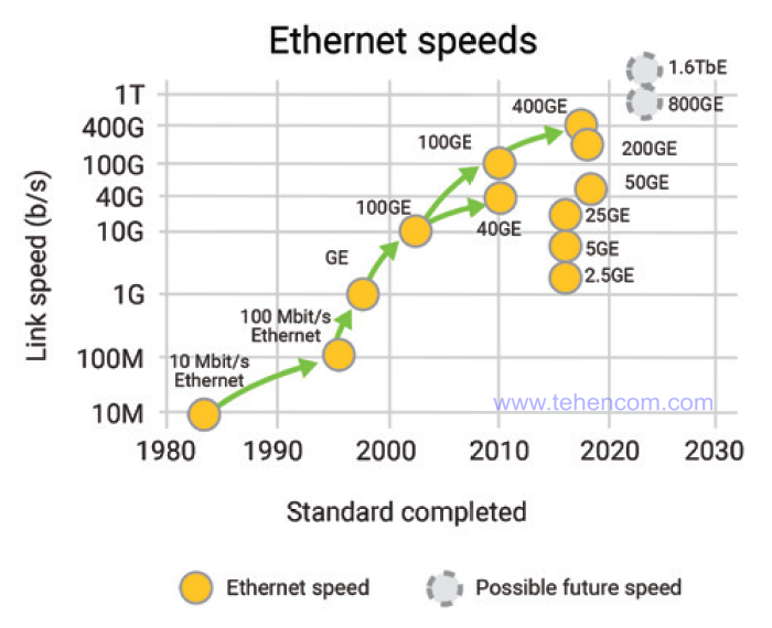
During the development and implementation of 40G speed, the market faced a paradoxical situation when several different implementations were simultaneously released by different manufacturers, including incompatible types of optical signal modulation: NRZ, RZ, DPSK and DQPSK. To avoid this scenario in 100G implementation, and given the significant investment in development of this technology, the Optical Internetworking Forum (OIF) has published a set of documents standardizing its key aspects.
Given the number of 10G and 40G implementations already in operation, it was decided that 100G technology should operate on the same physical channels as slower standards. In addition, existing networks already had a large number of reconfigurable optical input/output multiplexers (ROADMs) installed, and 50 GHz optical channel spacing was widely used in DWDM systems. Therefore, it was decided to keep 100G interoperability with these technologies as well.
As a result, NRZ-DP-QPSK modulation was recommended as the main type of optical signal modulation, capable of providing up to 112 Gbit / s over one optical channel, 50 GHz wide. The 112 Gb/s speed is sufficient for 100G Ethernet traffic to be transported using the Optical Transport Network (OTN), which is currently the most efficient core network implementation technology. The figure below shows how 40G and 100G traffic is injected into the OTU frame structure and further split at the OTL layer into multiple wavelengths for physical transmission over fiber.
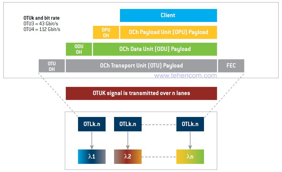
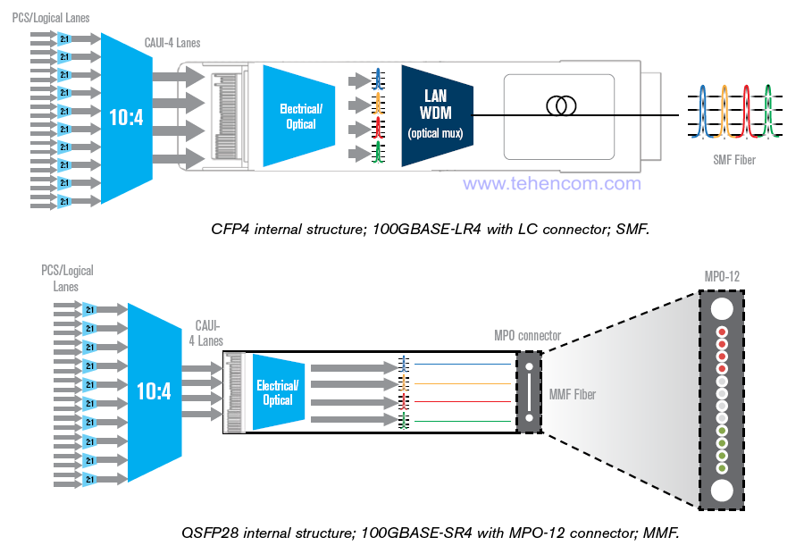
The IEEE 802.3ba standard provides for the transmission of a 100G Ethernet stream over single-mode fiber at four wavelengths (25G each). If a multimode fiber is used as the transmission medium, then the 100G Ethernet stream is split into four separate fibers (25G each). If 100G Ethernet traffic is transmitted over the OTN optical transport network, then it is also divided into four wavelengths (but already over 28G - an increase is necessary for OTN to work). In this case, the OTN protocol can provide automatic error detection and correction (FEC).
This figure shows the internals of a CFP4 converter with an LC connector that is used to carry 100G over single mode fiber, and a QSFP28 converter with an MPO-12 connector that is used to carry 100G over a group of multimode fibers.
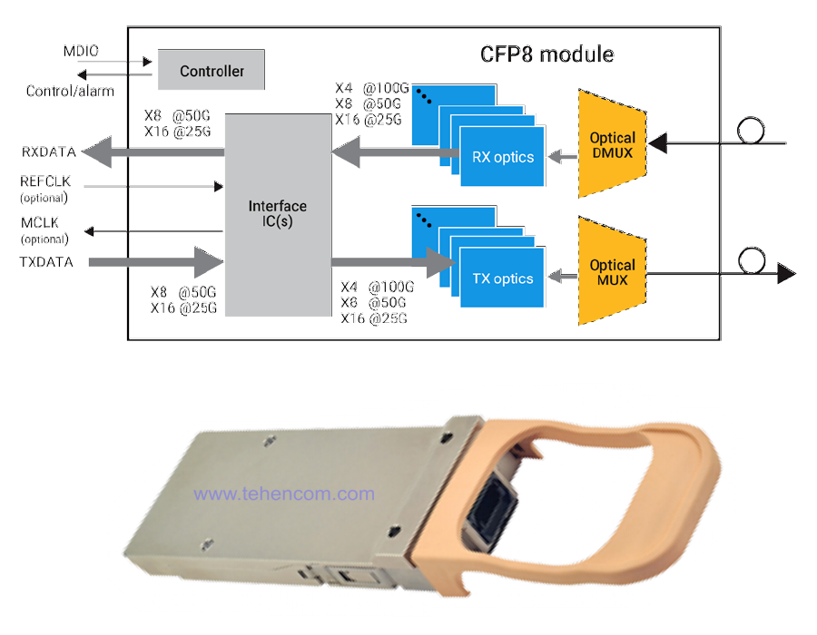
Specifications for 200G and 400G speeds are described in the IEEE 802.3bs standard. The key differences from 100G are: changed requirements for the physical layer and the mandatory use of the FEC error correction algorithm. The CFP8 module is standardized as a transceiver, with a transmission range over single-mode fiber up to 10 km. The CFP8 module can use two types of optical signal modulation (NRZ or PAM-4) and three options for splitting the speed by wavelength or individual fibers: 16 x 25 Gb / s, 8 x 50 Gb / s or 4 x 100 Gb / s. The block diagram and appearance of the CFP8 module are shown in this figure.
This was a brief overview of the development of data transmission technologies with speeds from 40G to 400G. See the full text of the review on pages 2 - 15 of this document:
100G and 400G Network Test Guide (English) (138 pages; 18 MB)
Flex Ethernet technology
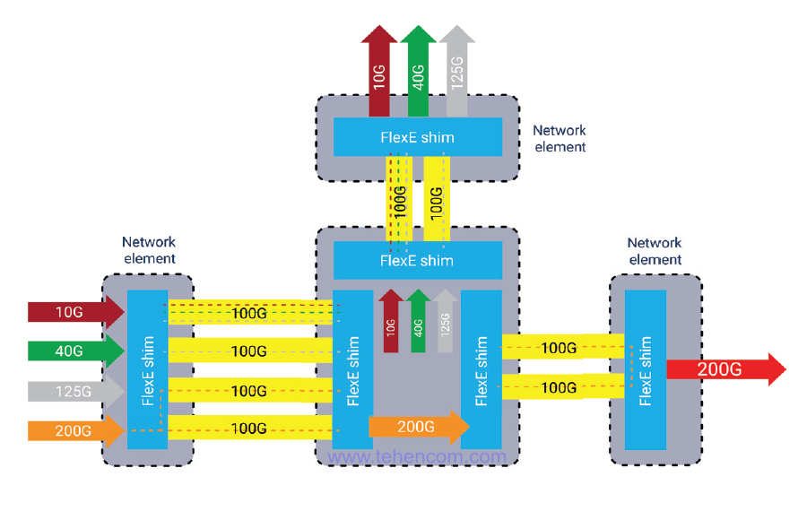
Flex Ethernet (flexible Ethernet) or FlexE for short was developed in 2016 by the Optical Internetworking Forum (OIF) consortium. This technology makes it possible to efficiently transfer data streams at speeds other than standard Ethernet speeds over standard Ethernet channels. For example, it is possible to transmit four streams over one 100G Ethernet channel, at a speed of 25G.
Flex Ethernet technology allows you to combine several standard 100G Ethernet channels into one faster one (for example, 400G) with the assignment of an individual MAC address to this combined channel. This mechanism is called Bonding.
The second important mechanism of Flex Ethernet is the ability to transmit data streams at lower speeds over a standard 100G Ethernet channel, for example, two 40G streams or three 25G streams. This mechanism is called Sub-rating.
The third component of Flex Ethernet technology, called Channelization, allows you to create transport channels with different speeds that are transparently transmitted over 100G Ethernet physical channels. An example of the implementation of the capabilities of Flex Ethernet technology is shown in this figure.
This is a brief introduction to Flex Ethernet. For the full text of the Flex Ethernet overview, as well as the new OTUCn extension of OTN optical transport technology, see pages 16 - 22 of this document:
100G and 400G Network Test Guide (English) (138 pages; 18 MB)
Measurements taken during commissioning and maintenance of 40G, 100G, 200G and 400G networks
Before launching and during the operation of networks with a speed of 40 Gbps and above, it is necessary to perform a set of measurements and tests. Each type of measurement checks individual parts of the network infrastructure for compliance with standards and specifications and allows you to identify and replace defective components in a timely manner.
Before commissioning, you must:
- check the quality of the connectors with optical microscope;
- perform reflectometry of individual fibers using
reflectometer;
- measure the insertion loss of fibers with a reflectometer or optical testers;
- measure the return reflection of the fibers using a reflectometer or optical testers;
- measure chromatic dispersion with HD analyzer and if necessary, make compensation;
- measure the polarization mode dispersion using PMD analyzer;
- measure spectral parameters and signal-to-noise ratio using optical spectrum analyzer;
- perform a set of necessary tests using telecommunications protocol analyzer.
During operation it is necessary:
- execute a set of standard tests using telecommunications protocol analyzer
- measure spectral parameters and signal-to-noise ratio using optical spectrum analyzer.
As you can see, during the operation of a working network, the main diagnostic tools are: a protocol analyzer and an optical spectrum analyzer. Proper use of these two devices is able to identify unreliable components at an early stage, which allows them to be replaced in a planned mode. Below on this page we will briefly review their main features.
However, if the cause of a failure or deterioration in the quality of the network cannot be determined using the protocol analyzer and the spectrum analyzer, then additional instruments must be used: a reflectometer, a dispersion meter, a microscope.
Detailed instructions for testing high-speed networks are provided on pages 82 - 133 of this document:
100G and 400G Network Test Guide (English) (138 pages; 18 MB)
Telecom protocol analyzer application
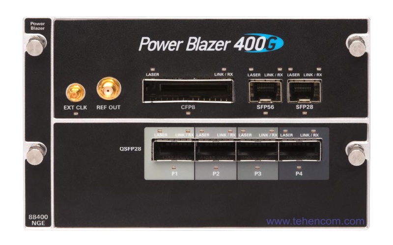
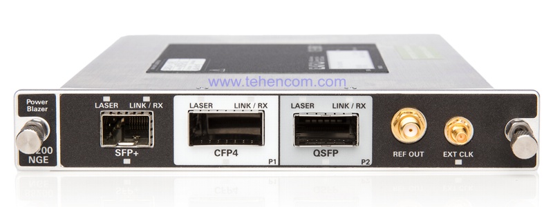
Regular network health checks and troubleshooting are performed using a protocol analyzer. Typically protocol analyzers are available as modular instruments such as EXFO FTB-4-Pro with FTBx-88400NGE module (for speeds up to 400G) or EXFO FTB-2-Pro with module FTBx-88200NGE (for speeds up to 100G). But there are also compact, non-modular instruments, such as the analyzer series EXFO MAX-800.
This photo shows the appearance of the FTBx-88400NGE module for testing networks up to 400G.
This photo shows the appearance of the FTBx-88200NGE module for testing networks up to 100G.
The protocol analyzer allows you to check various elements of the network infrastructure, from the quality of transceivers (CFP, QSFP, etc.) to the decoding and inspection of Ethernet, OTN, SDH, CPRI-OBSAI, Fiber Channel, etc. packets. Also, the protocol analyzer can generate various types of traffic and thus conduct network stress tests to determine a stable transfer rate, optimal launch parameters for various services, and many other parameters with which you can fine-tune the network for its trouble-free operation.
This screenshot shows a set of tests that the EXFO FTBx-88200NGE protocol analyzer module can perform. In addition to the classic RFC 2544 and BERT tests, it is worth emphasizing the support for advanced testing methods EtherSAM (Y.1564) and RFC 6349, which allow efficient testing and optimization of the IP network layer and TCP layer.
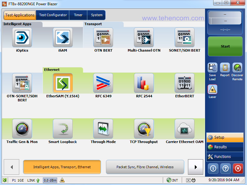
Since the protocol analyzer is a complex instrument, its effective use requires deep theoretical knowledge and practical experience. Detailed instructions for using protocol analyzers are provided on pages 103 - 133 of this document:
100G and 400G Network Test Guide (English) (138 pages; 18 MB)
Application of optical spectrum analyzer
An optical spectrum analyzer is often used in conjunction with a protocol analyzer to find sources of faults that reside at the physical layer of a network infrastructure. The optical spectrum analyzer allows you to detect faulty optical transmitters, optical amplifiers, input-output multiplexers, optical filters and other elements.
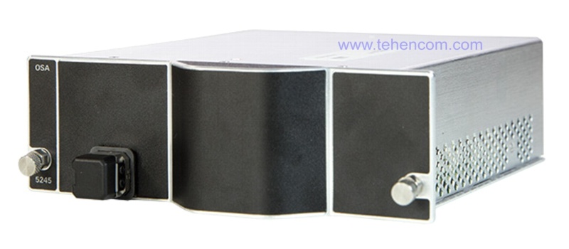
Typically, optical spectrum analyzers are available as modular instruments, such as EXFO FTB-2-Pro with module FTBx-5245. But there are also non-modular desktop devices. This photo shows the exterior of one of the most advanced optical spectrum analyzer modules to date, the EXFO FTBx-5245.
The optical spectrum analyzer allows you to see the distribution of signal power in the fiber depending on the wavelength. This information is very important for assessing the correctness of the operation of the main elements of the physical layer of the network, such as reconfigurable ROADM multiplexers, EDFA amplifiers, optical transmitter lasers SFP, CFP, QSFP, etc.
This screenshot shows the spectrum of a real network using ROADM. Ten active 10G channels are located in the central part of the graph between 1545 nm and 1553 nm. On the right side of the graph, starting from a wavelength of 1553 nm, there are several active channels with a speed of 40G.
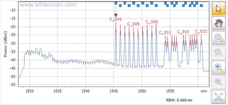
In addition to a graphical display of the spectrum shape, which can be used to quickly assess the condition of the network, the optical spectrum analyzer automatically measures the main parameters of each of the active channels and compares the results with the requirements of the corresponding standard.
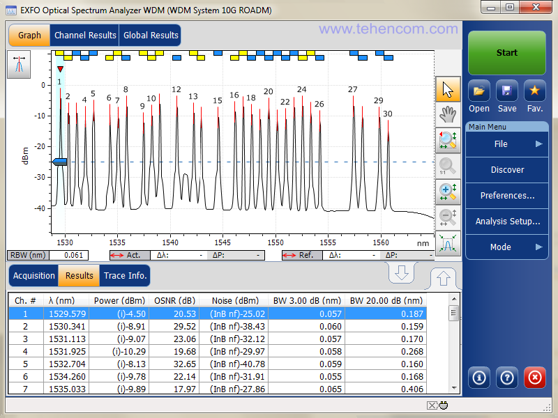
The screenshot below shows the spectrum of a typical DWDM system with a channel spacing of 100 GHz (about 0.8 nm). The transmission rate in each channel is 10G, plus reconfigurable optical input / output multiplexers (ROADM) are used. At the top is a graph of the spectrum (optical power in dBm versus wavelength in nm). The graph clearly shows all active channels (30 pcs.) And about a dozen inactive channels.
Below the graph is a table with detailed data for each channel: channel center wavelength, channel power, signal to noise ratio (OSNR), noise level in each channel, -3dB channel width and -20dB channel width. For a specialist, this information makes it possible to quickly assess the health of the network and proactively detect and replace problematic elements, such as EDFA amplifiers and channel I/O multiplexers.
An optical spectrum analyzer, like a protocol analyzer, is a fairly complex instrument. To use it effectively, theoretical and practical training is required. Detailed instructions for using optical spectrum analyzers are given on pages 82 - 100 of this document:
100G and 400G Network Test Guide (English) (138 pages; 18 MB)
Recommended measuring instruments
Above on this page was a list of measurements to be taken when commissioning and maintaining 40G, 100G and faster networks. In this section, we present specific models of instruments that are designed to carry out the required measurements and tests.
List of recommended instruments and equipment:
- checking the quality of optical connectors: EXFO FIP-400B;
- reflectometry of optical fibers: EXFO FTB-700C or EXFO FTBx-700C;
- measurement of insertion loss and back reflection: EXFO FTB-3930;
- measurement of chromatic dispersion and PMD: EXFO FTB-5700;
- measurement of optical spectrum parameters: EXFO FTBx-52x5 or EXFO FTB-5235;
- protocol analysis: EXFO FTB-1 Pro or EXFO FTB-2 Pro.
Additional information on this topic
This page contains the main information from a detailed guide compiled by the company's specialists. EXFO, summarizing all the important information on the technologies of modern high-speed networks. Also in this manual are models of instruments for carrying out all types of measurements and describes the methods for their correct application. The full text of the manual can be downloaded in PDF format:
100G and 400G Network Test Guide (English) (138 pages; 18 MB)
You may also be interested in this article:
ITU-T Y.1564 Test Method for Activating Ethernet Services
If you need detailed pricing information or technical advice on choosing the best measurement equipment for your application, just call us or write to us at E-mail and we will be happy to answer your questions.