Laboratory Optical Spectrum Analyzer (600nm - 1725nm) Anritsu MS9740B
Product code: 1000364
Add item to cart. Our specialist will coordinate with you the complete set, tell you the price and delivery time.
Price on request
SHORT DESCRIPTION
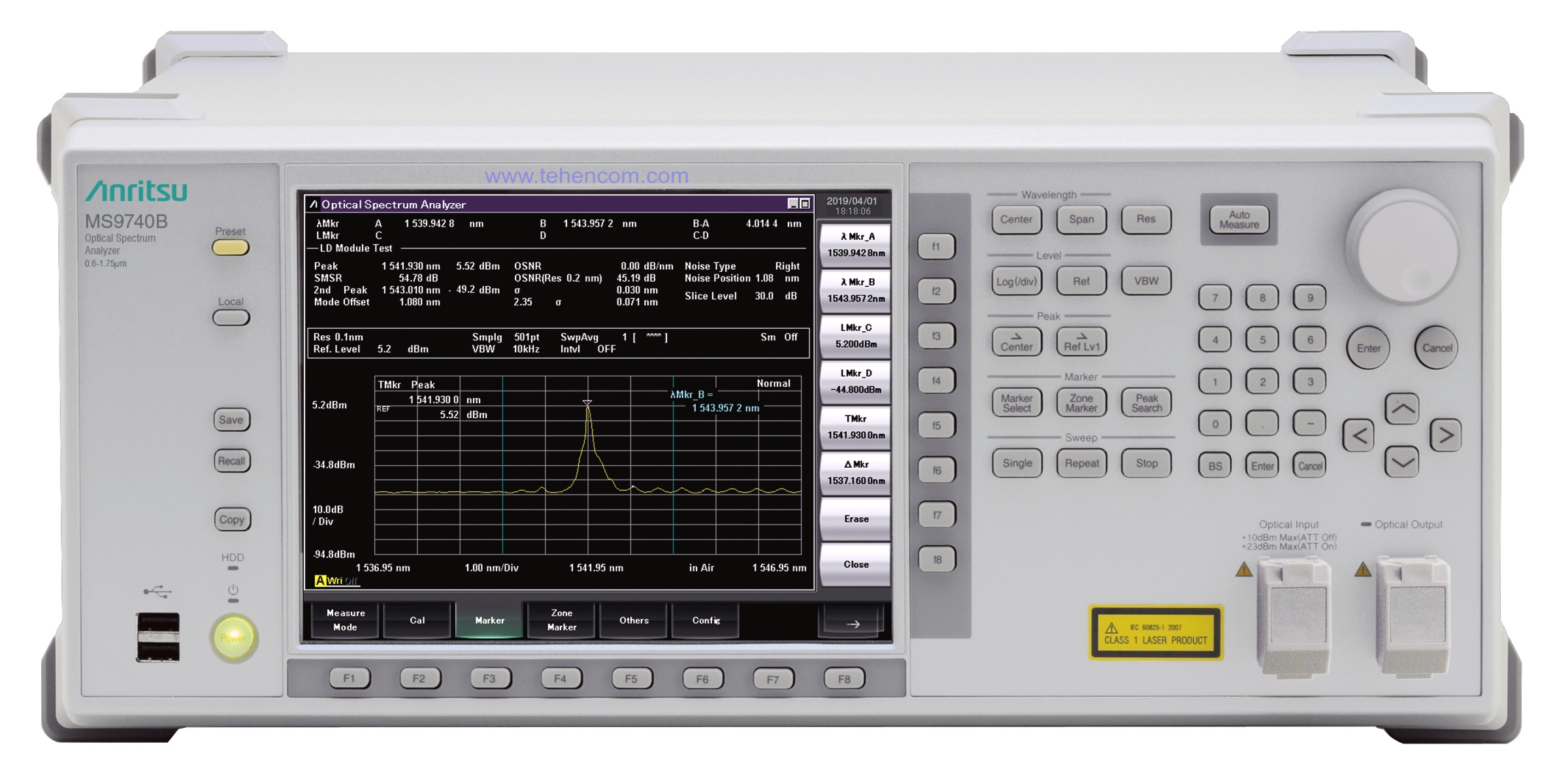
In 2019, a Japanese company Anritsu released an updated model laboratory optical spectrum analyzer Anritsu MS9740B. Compared to its predecessor, the MS9740A, the new analyzer is twice as fast in measuring and contains many improvements. At the same time, the size of the case and the location of the interface elements have not changed.
The Anritsu MS9740B analyzer is optimized for the development and production control of all types of fiber optic devices with operating wavelengths from 600 nm to 1725 nm. To speed up the configuration and measurements, it contains nine configured modes for solving typical tasks (different types of lasers, EDFA amplifiers, etc.). You can download a full description of all the characteristics of the Anritsu MS9740B optical spectrum analyzer below on this page in the section Documentation.
Main characteristics and models:
Wavelength range: 600 nm - 1725 nm.
Dynamic Range: -90 dBm to +23 dBm.
Wavelength measurement error: 0.02 nm. Power measurement error: 0.4 dB.
Typical measurement time 350 ms. Built-in source for calibration (option).
Nine modes optimized for typical measurements: DFB-LD, FP-LD, LED, LD Module, PMD, Optical Amplifier, Optical Amplifier WDM, WDM Filter, WDM Spectrum.
DWDM support with 50 and 100 GHz channel spacing.
21.3 cm screen (800 x 600 resolution). Interfaces: Ethernet (standard), IEEE-488 (GPIB) (option).
Weight: 15 kg. Dimensions: 426 x 177 x 350 mm. Working temperature: from +5°С to +45°С.
Professional analyzer for laboratory and production
Need a portable analyzer for telecom? see model EXFO FTB-5235.
You just need to measure DWDM channel power? see model EXFO FOT-5205.
Want to see the full list? Go to the main page by optical spectrum analyzers.
Nine customized modes for solving typical tasks
Each type of measured optical device has its own spectrum features and, as a result, the set of parameters that need to be measured is different. Depending on the task to be solved, you can select Anritsu MS9740B from the analyzer menu any of nine pre-configured modes to measure what you need for a specific type of equipment.
These nine modes are designed to measure:
- DFB-LD (Distributed Feedback Laser - laser with distributed feedback)
- FP-LD (Fabry-Perot Laser Diode - Fabry-Perot laser diode)
- LED (Light Emitting Diode - LED)
- Laser Diode Module (Optical-transceiver - optical transceiver)
- PMD (Polarization Mode Dispersion - polarization mode dispersion (PMD))
- Optical Amplifier (optical amplifier)
- Optical Amplifier WDM (amplifier in wavelength division multiplexing mode)
- WDM Signal (Wavelength Division Multiplexed Signal)
- WDM Filter (optical filter for wavelength division multiplexing systems)
Each of these modes is configured in such a way that all important indicators of the measured device are conveniently displayed on one screen. This is very practical and saves a lot of time both in scientific research and in high-speed automatic testing during production.
Some of these modes are shown below. Detailed information about all the features and technical characteristics of the Anritsu MS9740B analyzer is available in PDF format in the section Documentation further on this page.
Measurement of optical filters parameters
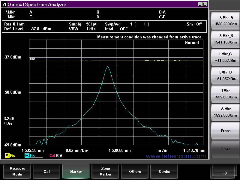
The Anritsu MS9740B analyzer is effectively used to measure the characteristics of optical filters, attenuators and other similar devices. To do this, at the first stage, the reference signal of an external source of broadband radiation is measured (without filter connection). At the second stage, the filter under study is switched on between the source and the analyzer and the measurement is taken again. The difference between the two measurements determines the parameters of this filter or other device. Please note that for this type of measurement dynamic range analyzer MS9740B exceeds 58 dB.
This screenshot shows the spectra of two optical signals. The upper yellow graph is the radiation level of a broadband source connected to the analyzer without a filter (reference signal). The blue graph is the signal attenuated by the filter under study.
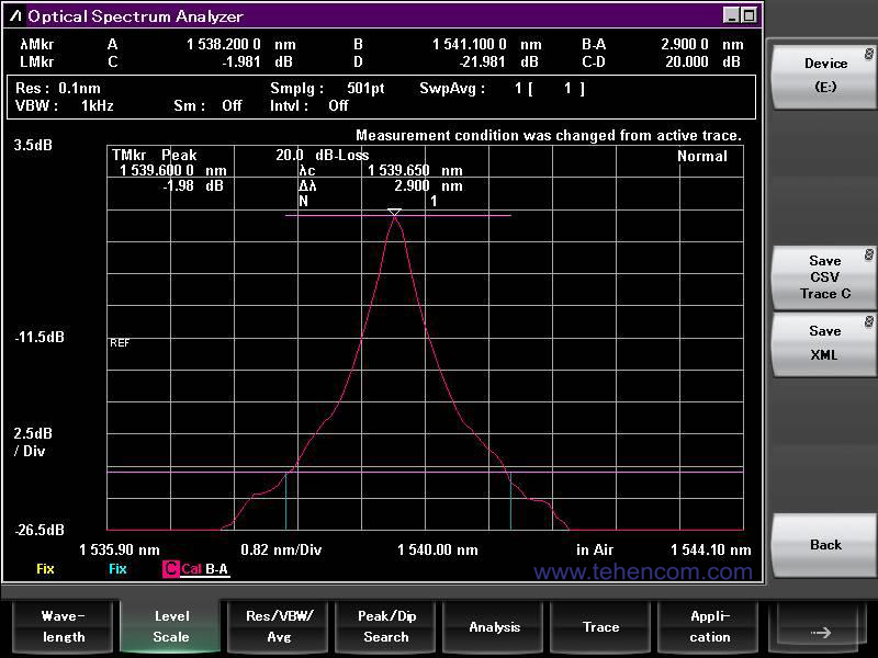
The real attenuation parameters of the filter at different frequencies, its amplitude-frequency response (AFC), are calculated as the difference between these two measurements. This screenshot shows the frequency response of the studied optical filter.
To speed up the process with a large amount of testing, additional optical switches can be used, as shown in the figure below.

Measurement of parameters of WDM optical amplifiers
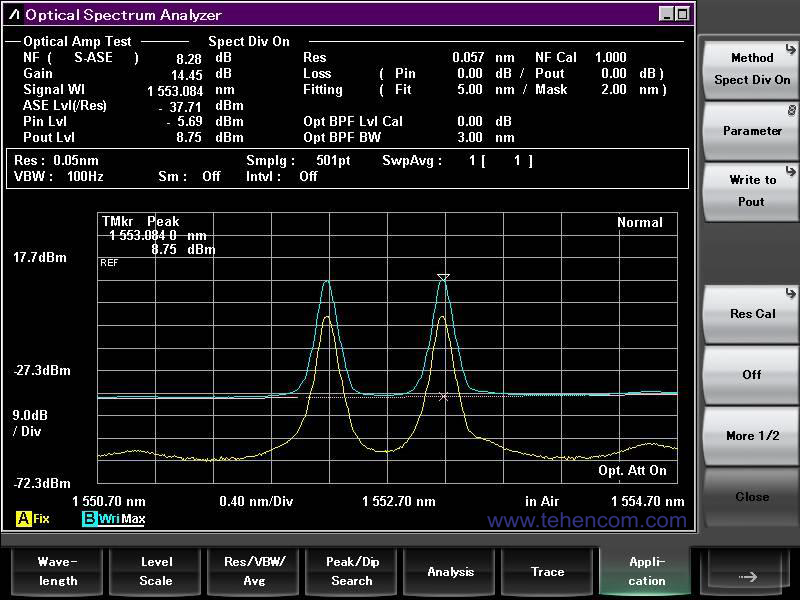
When choosing a mode Optical Amplifier WDM, on the screen of the Anritsu MS9740B optical spectrum analyzer for each WDM channel, measurement results specific to EDFA optical amplifiers are displayed, such as: gain (gain), noise figure (noise figure), amplified signal peak width (amplified optical peak wavelength) and others options.
An example of the MS9740B screen in this mode is shown in the screenshot below. The measurement procedure includes two stages: first, an optical signal source is directly connected to the spectrum analyzer (lower yellow graph), and then the optical amplifier under test is connected between the signal source and the analyzer (upper blue graph).
Measurement of parameters of optical transceivers
Mode Laser Diode Module, Anritsu MS9740B Spectrum Analyzer, is used to measure key optical characteristics of transceivers. If you supplement the measuring stand with a bit error analyzer (BERT), for example, Anritsu MP2100B, then you can additionally test the operation of the electrical part of the transceiver and measure the error rate depending on the parameters of the input signal. An option for connecting equipment using two measuring instruments and optical attenuators (O-ATT) is shown in this figure.
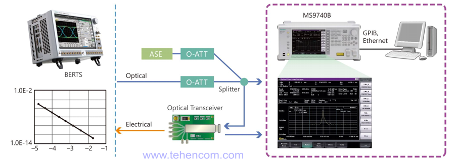
In addition to high accuracy and speed of measurements, the obvious advantages of the Anritsu MS9740B analyzer include the fact that, regardless of the type of radiator of the transceiver under test, all measurements are shown on one summary screen, which is located above the optical spectrum graph.
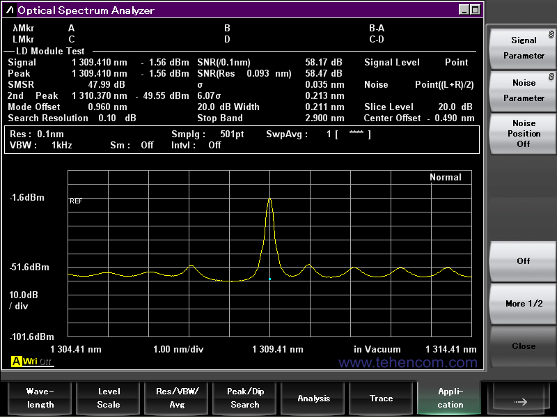
For the spectrum of the transceiver, the following are measured and calculated: the central wavelength, amplitude, signal-to-noise ratio (SNR), standard deviation, side mode suppression ratio (SMSR - Side Mode Suppression Ratio) and other parameters. The appearance of the Anritsu MS9740B screen in this mode is shown in the screenshot below.
Built-in source for calibration
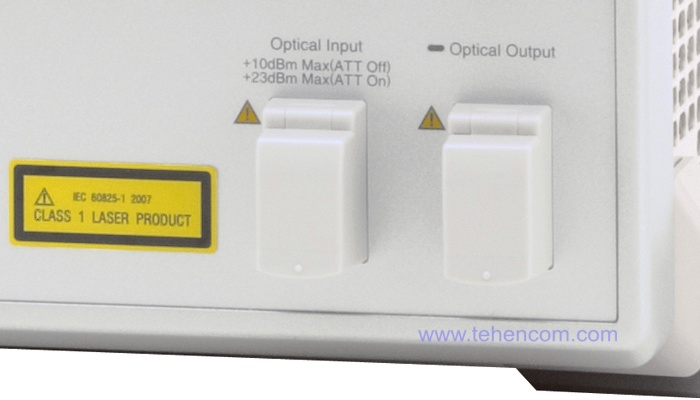
On the right side of the front panel of the Anritsu MS9740B analyzer, there is an optical connector (the inscription on the Optical Output photo) of a reference radiation source with a wavelength of 1550 nm and a stability of ±0.04 dB. This source is installed in the analyzer when ordering option MS9740B-002. If option 002 is not available, then a separate external source of stable radiation must be used for calibration.
Modification of the analyzer to work with 62.5 µm multimode fiber
As standard, the Anritsu MS9740B spectrum analyzers can measure optical signals on G.652 single-mode and 50/125 µm multimode fibers. To work also with multimode fiber 62.5/125 µm, a modification of the analyzer is available MS9740B-009 which uses a different type of optical signal receiver.
The MS9740B-009 supports G.652 single mode, 50/125 µm multimode, and 62.5/125 µm multimode, but some of the performance of the MS9740B-009 when measuring a signal from single mode fiber is worse than that of the standard version of the MS9740B analyzer. For more information about the differences between these two modifications of the device, see below on this page in the section Documentation.
Design features of the Anritsu MS9740B analyzer
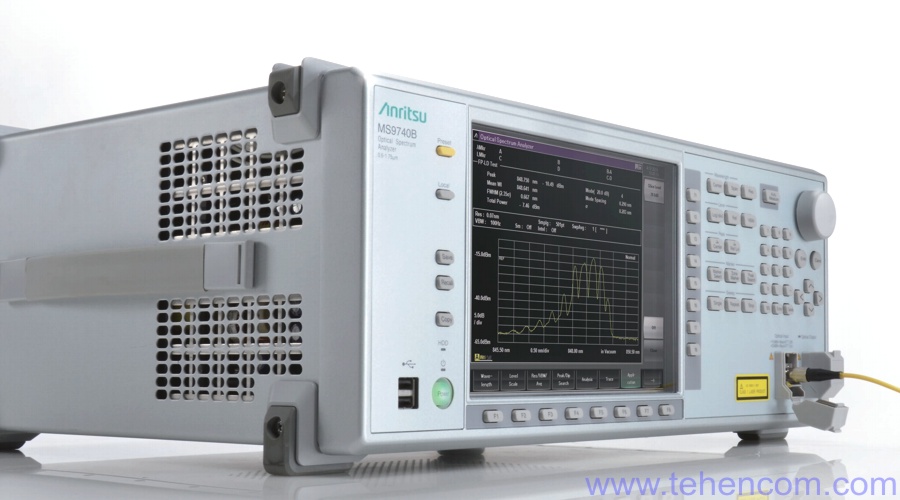
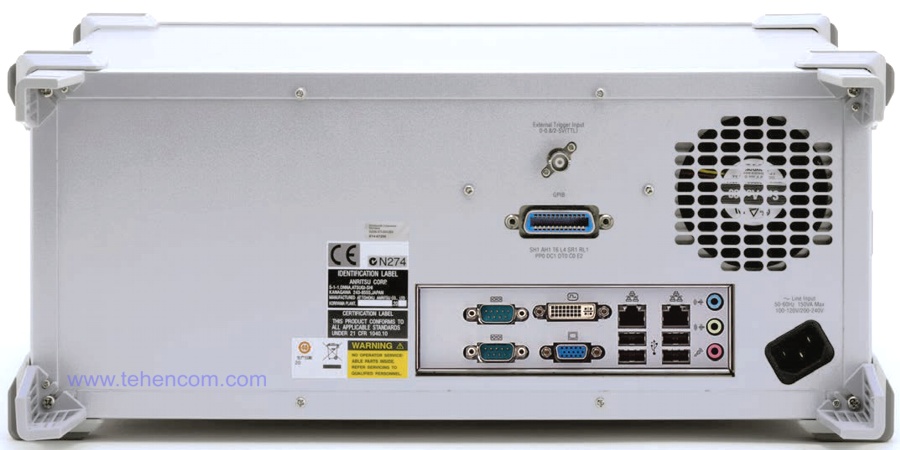
The Anritsu MS9740B optical spectrum analyzer is made in a classic laboratory case. On the front panel there are controls and two USB connectors for connecting flash drives. All communication connectors are located on the rear panel: a standard Ethernet interface and an optional IEEE-488 (GPIB) interface for connecting the analyzer to a computer, connectors for an external display, and four additional USB connectors for connecting a mouse, keyboard, and other peripherals.
Documentation
This PDF documentation contains the most comprehensive description of the Anritsu MS9740B laboratory optical spectrum analyzer features, specifications and modes of operation:
Description and characteristics of the analyzer Anritsu MS9740B (in English) (16 pages; 7 MB)
Anritsu MS9740B Analyzer User Manual (English) (322 pages; 5 MB)
Anritsu MS9740B Analyzer Programming Guide (English) (316 pages; 2 MB)
And here you can find our tips and other useful information on this topic:
Testing 40G, 100G, 200G and 400G networks - a detailed guide
How to buy equipment cheaper - discounts, special prices, demo and used devices
To simplify the process of choosing an optical spectrum analyzer, you can use our experience and recommendations. We have over 20 years of practical supply experience and can immediately answer many questions about models, options, delivery times, prices and discounts. This will save your time and money. For this it's simple call us or write to us at Email and we will be happy to answer your questions.