Anritsu MW82119B Passive Intermodulation Analyzer (PIM) Series up to 3 GHz
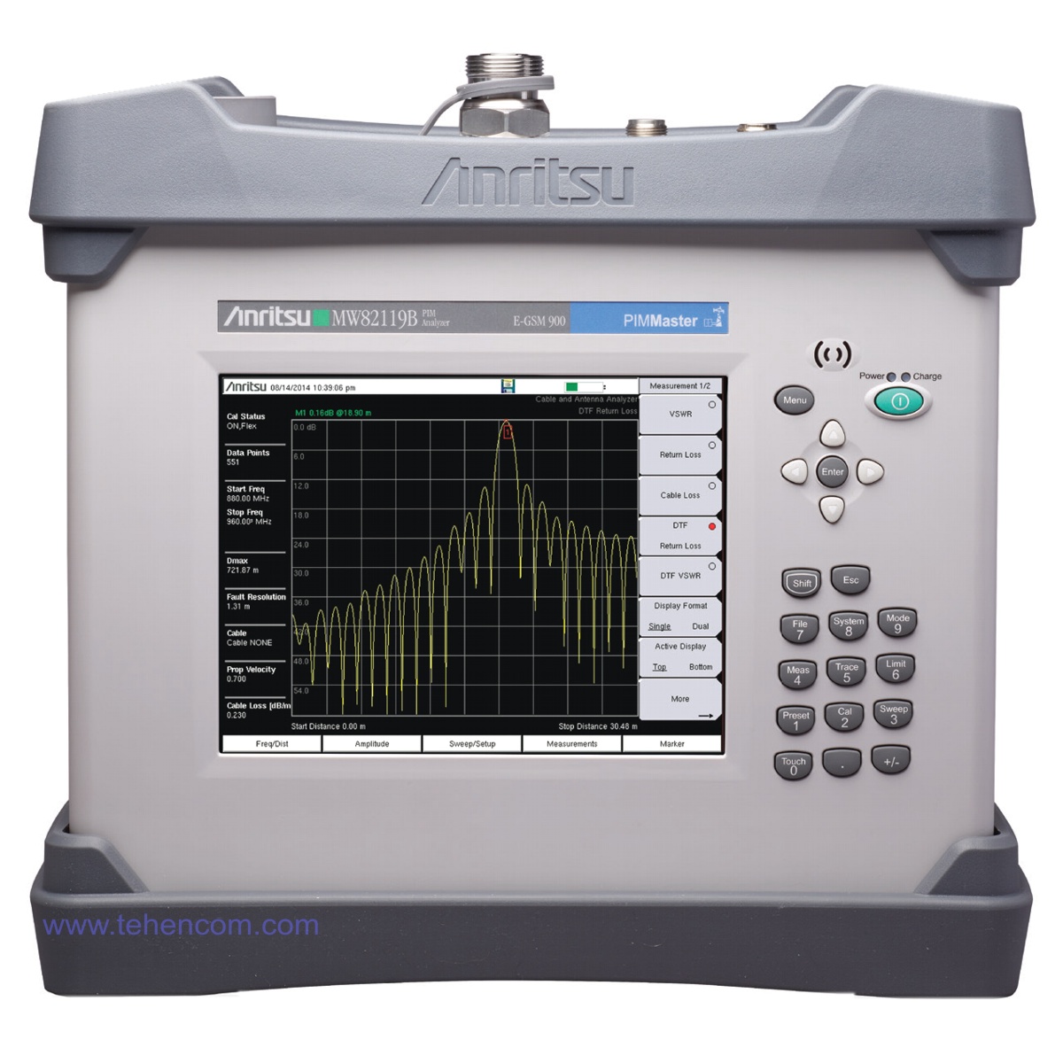
Product code: 1000182
Add item to cart. Our specialist will coordinate with you the complete set, tell you the price and delivery time.
Price on request
SHORT DESCRIPTION
Analyzer Anritsu PIM Master MW82119B allows you to identify sources of passive intermodulation distortion (PIM) inside the antenna-feeder path of the mobile network infrastructure, as well as outside it - in the immediate vicinity of the transmitting antennas. PIM measurement is an important part of the quality assurance of existing 3G networks. And when deploying 4G and 5G networks, which use large channel widths and complex modulation types, measuring and minimizing the PIM level is absolutely necessary. The portable Anritsu PIM Master MW82119B is specially designed to effectively solve this problem. You can download a full description of all the characteristics of Anritsu MW82119B below on this page in the section Documentation.
Main characteristics:
Frequency: 698 MHz - 806 MHz for LTE 700 (Model MW82119B-0700)
Frequency: 710 MHz - 845 MHz for APT 700 (Model MW82119B-0701)
Frequency: 791 MHz - 862 MHz for LTE 800 (Model MW82119B-0800)
Frequency: 824 MHz - 894 MHz for Cellular 850 (Model MW82119B-0850)
Frequency: 880 MHz - 960 MHz for E-GSM 900 (Model MW82119B-0900)
Frequency: 885 MHz - 1920 MHz for E-GSM 900 with IM 2 (Model MW82119B-0902)
Frequency: 1710 MHz - 1880 MHz for DCS 1800 (Model MW82119B-0180)
Frequency: 1710 MHz - 2155 MHz for PCS/AWS 1900/2100 (Model MW82119B-0194)
Frequency: 1920 MHz - 2170 MHz for UMTS 2100 (Model MW82119B-0210)
Frequency: 2500 MHz - 2690 MHz for LTE 2600 (model MW82119B-0260)
Measurement of the passive intermodulation level. Measurement of the distance to the source of passive intermodulation inside the feeder and outside the antenna (over the air).
AFA analyzer in the range of 2 MHz - 3 GHz (option 331).
Power measurement with external sensors (option 19).
More than 3 hours of work from the built-in rechargeable battery.
21.3 cm touchscreen (800 x 600 resolution). Interfaces: USB, Ethernet.
Working temperature: from -10°С to +55°С. Dust and splash protection during operation according to IP54.
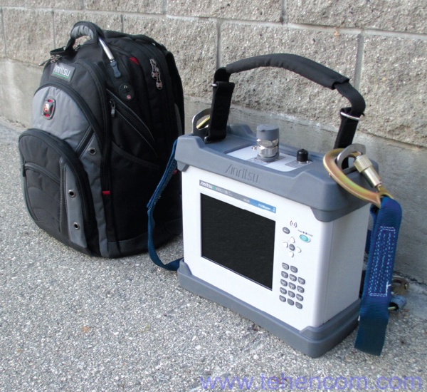
Weight: 9.2 - 12.4 kg (varies by model). Dimensions: 350 x 314 x 152 mm.
Finding and Eliminating PIM Sources to Optimize 3G, 4G and 5G Networks
Required spectrum analysis and signal demodulation mobile connection? Watch the series Anritsu MT821xE.
Need compact feeder analyzer to measure SWR? See device Anritsu Site Master S331L.
Want to see the full list of models? See section Devices for mobile and wireless communication.
DETAILED DESCRIPTION
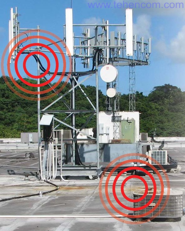
The signal emitted by a mobile communication antenna has a power of several tens of watts, and the width of its spectrum for 4G and 5G networks is several tens of MHz. When this signal passes through the antenna-feeder path and further on the air, it encounters various inhomogeneities, which can lead to multiplication of the frequency components of the signal and the formation of additional frequencies. This effect is called passive intermodulation (PIM for short). Within the AFU, PIM sources can be: corroded connectors, poorly tightened connectors, gas dischargers, filters, the feeder itself, an antenna, etc. Outside the AFU, any metal object located in the radio signal radiation zone of the antenna can become a PIM generating source. Particularly strong intermodulation products are generated on large metal objects,
Why has so much attention been paid to the PIM effect lately? One of the reasons is that the frequency of the intermodulation products very often falls into the uplink range, which leads to a significant degradation of the coverage area, a decrease in the data rate and disconnections. Therefore, along with the usual measurements of the SWR of the feeder and the distance to the heterogeneity according to the SWR in the feeder, which have long been standard, it is also necessary to measure the PIM level and the distance to the heterogeneity according to the PIM.
The PIM Master MW82119B analyzer belongs to the third generation of measuring instruments of this class from the Japanese company Anritsu. This analyzer allows you to completely solve the problem of finding and eliminating PIM sources in mobile communication systems. It also allows you to measure SWR, power, feeder losses and determine the distance to inhomogeneities in the feeder. That is, it contains in a compact, dust-proof, moisture-proof case all the necessary tools to optimize the site.
Track PIM level changes over time
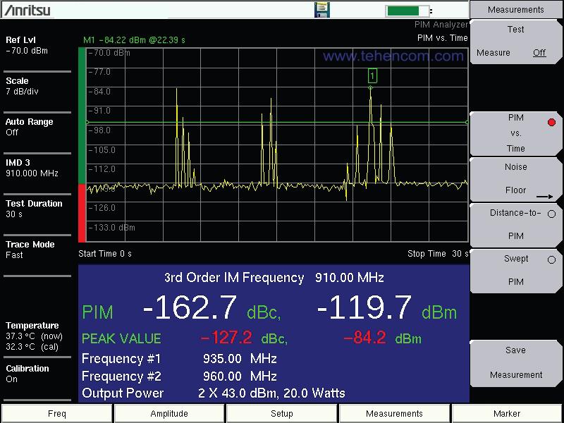
The basic measurement that is carried out at the facility is the measurement of the PIM level over a period of time. It can be used to determine the stability of the system and identify the sources of short-term generation of PIM. During this test, the Anritsu MW82119B repeatedly feeds two carriers into the feeder and measures the third, fifth, or seventh order intermodulation power, plotting the measured value. The test usually takes a few minutes. Tapping of suspicious feeder sections can be used, since PIM often occurs in places affected by corrosion, and they usually change their properties under mechanical stress.
In this screenshot of the Anritsu PIM Master MW82119B analyzer, a PIM power measurement is performed over a 30 second time period. As shown at the bottom of the analyzer screen, it generates two carriers: 935 MHz and 960 MHz, 20 W each. At these carrier frequencies, the third order intermodulation product is located at 910 MHz. For most of the test, the power of this component was at the level of -119 dBm, but several times it jumped to values of about -90 dBm. As you can see, this type of test is well suited for assessing the stability of the PIM level over time.
Determination of distances to PIM sources
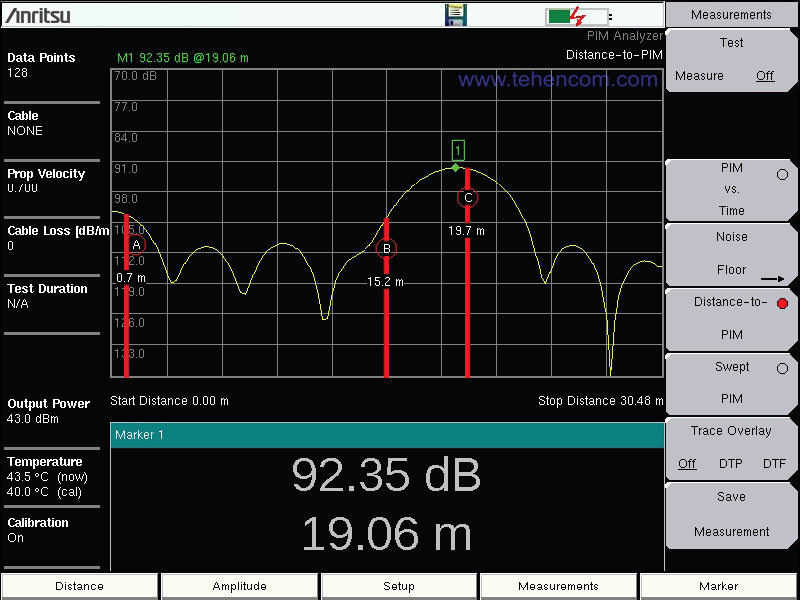
The main task of the Anritsu MW82119B analyzer is to identify all sources of passive intermodulation that may interfere with the normal operation of the base station. And Anritsu PIM Master copes with this task in the best way. In addition to displaying a distance plot to PIM sources (called DTP), the MW82119B shows the exact location of these sources, allowing them to be located with a resolution of up to 10 cm.
This screenshot shows how the Anritsu MW82119B analyzer automatically detected the presence of three PIM sources and placed three vertical red markers on the graph in the places of their detection at distances: 0.7 meters, 15.2 meters and 19.7 meters.
Measuring the level of interference at the frequency of the intermodulation component
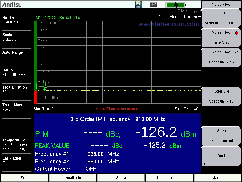
This test determines the presence and level of interference at the frequency of the intermodulation product of interest. This test is necessary because nearby mobile phones and other radio transmitting devices can cause significant interference at exactly the frequency of the intermodulation product that you want to measure. When there are no interfering transmitters nearby, the power level recorded in the Noise Floor mode is about -120 dBm or even less.
This screenshot shows the screen of the Anritsu MW82119B analyzer when checking the noise level at a frequency of 910 MHz. During this measurement, the MW82119B does not apply two-carrier power to the feeder, but simply measures the interference level at a user-specified intermode frequency (3rd, 5th, or 7th).
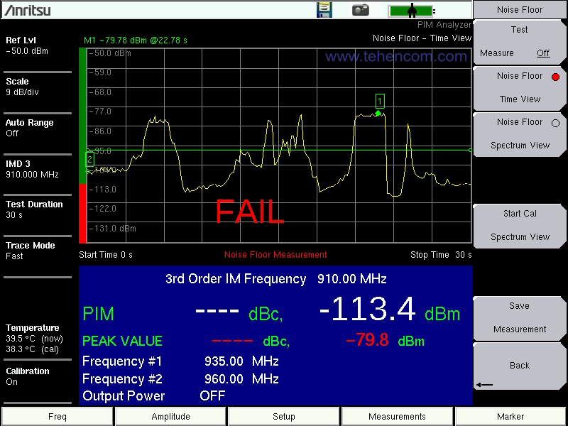
And this screenshot shows the screen of the Anritsu MW82119B analyzer in the presence of interference at a frequency of 910 MHz. The horizontal green line is set to -97 dBm, which is defined as the limit in this case. In such an interference environment, accurate PIM measurements cannot be made. The solution may be to slightly change the frequencies of the Frequency 1 and Frequency 2 generation, which will cause a corresponding shift in the frequencies of the intermodulation products. The second solution is to temporarily disable interfering radio transmitters.
Additional features and measurement modes of the Anritsu PIM Master MW82119B analyzer
The main feature of the Anritsu solution is that the MW82119B analyzer is able to find PIM sources not only inside the antenna-feeder path, but also outside it. Over the years of the struggle of mobile operators with the problem of PIM around the world, exhaustive statistics have accumulated. As practice shows, more than half of all significant PIM sources are outside the AFU in the area of the antenna radiation pattern. These can be metal mounting structures, rusty tin on roofs, and even reinforcement inside reinforced concrete floors. With the Anritsu MW82119B analyzer, you can find all these sources and take the necessary measures, such as antenna reorientation or shielding.
Separately, it is worth noting the presence of a full-fledged built-in AFU analyzer, similar in capabilities to the device Anritsu S331E. This functionality, added with option 0331, allows you to not only measure feeder SWR, cable loss and other standard functions, but to superimpose the DTP (distance to PIM) trace over the DTF (distance to discontinuity) trace, which opens up new opportunities for optimizing equipment performance.
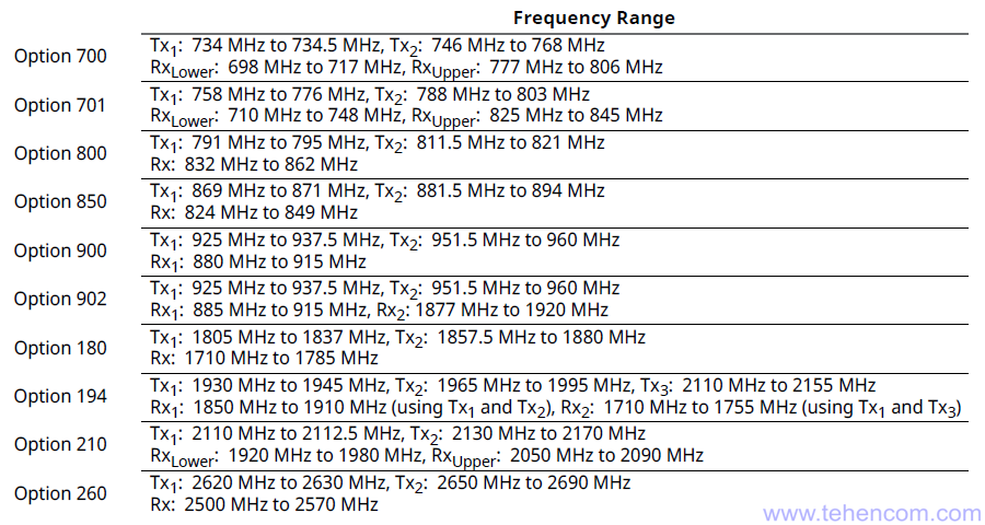
Frequency ranges of various modifications of the Anritsu PIM Master MW82119B analyzer
Below are data on the generation frequencies of two carriers (Tx1 and Tx2), as well as on the measurement frequencies of the intermodulation component Rx. For a complete list of technical characteristics, including generation power, noise level and other parameters, see below on this page in the section Documentation.
Anritsu MW82119B PIM Analyzer Package
When ordering an Anritsu MW82119B series analyzer, you must specify the operating frequency range of the instrument. There are 10 modifications in total. All of them are listed in this table. For detailed values of the operating frequencies of generation and analysis frequencies of the MW82119B series instruments, see this page in the section Documentation.
| Name | Short description |
| Anritsu MW82119B-0700 | PIM Analyzer for LTE 700 MHz (North America), 698 MHz to 806 MHz |
| or | |
| Anritsu MW82119B-0701 | PIM analyzer for APT 700 MHz networks, frequencies from 710 MHz to 845 MHz |
| or | |
| Anritsu MW82119B-0800 | PIM analyzer for 800 MHz LTE networks, frequencies from 791 MHz to 862 MHz |
| or | |
| Anritsu MW82119B-0850 | PIM analyzer for cellular networks in the 850 MHz band, frequencies from 824 MHz to 894 MHz |
| or | |
| Anritsu MW82119B-0900 | PIM analyzer for E-GSM 900 MHz networks, frequencies from 880 MHz to 960 MHz |
| or | |
| Anritsu MW82119B-0902 | PIM analyzer for standard networks E-GSM 900 with the ability to measure the second harmonic, frequencies from 885 MHz to 1920 MHz |
| or | |
| Anritsu MW82119B-0180 | PIM analyzer for standard networks DCS 1800 MHz, frequencies from 1710 MHz to 1880 MHz |
| or | |
| Anritsu MW82119B-0194 | PIM analyzer for PCS/AWS 1900/2100 networks, 1710 MHz to 2155 MHz |
| or | |
| Anritsu MW82119B-0210 | PIM analyzer for 2100 MHz UMTS networks, frequencies from 1920 MHz to 2170 MHz |
| or | |
| Anritsu MW82119B-0260 | PIM analyzer for standard networks LTE 2600 MHz, frequencies from 2500 MHz to 2690 MHz |
| - | Power cable |
| 40-187-R | Power Supply |
| 2000-1786-R | Carry bag providing access to the screen |
| 2000-1714-R | Shoulder strap with carabiners |
| 2000-1691-R | Stylus |
| 2000-1797-R | Screen protector |
| 1091-422-R | Adapter 7/16 DIN(f) - 7/16 DIN(m), 50 Ohm. Designed to reduce wear on the analyzer input connector |
| 633-75 | Rechargeable Li-Ion battery (installed inside the instrument) |
| 806-141-R | Car Cigarette Lighter Charging Adapter (12V, 60W) |
| 2000-1371-R | Ethernet cable, 2 meters |
| 3-2000-1498 | USB cable (A - mini B), 3 meters (for connecting the analyzer to a computer) |
| - | 1 year warranty (can be extended to 3 and 5 years) |
Options and accessories for Anritsu MW82119B PIM analyzers
In addition to the standard equipment listed above, the MW82119B Series analyzer can be equipped with several options to expand its capabilities. The main option is an antenna-feed path analyzer for measuring SWR and distance to fault. This option number is 0331. A high-precision power sensor can also be added and measurements can be tied to the terrain using GPS.

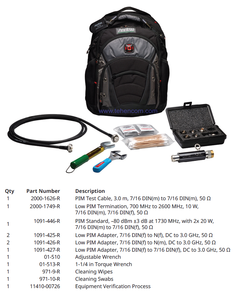
To connect the MW82119B analyzer to the measurement object, you need a phase-stable cable with a low level of PIM, as well as a set of adapters for popular connector types. Adapters must also have a low PIM level. It is also advisable to use a torque wrench with a normalized tightening force for the connectors. And in order to regularly check the accuracy of the measurement, it is necessary to have a PIM standard and a powerful matched load with a guaranteed low PIM level complete with the device. All these accessories are collected in set 2000-1745-R, which also includes a durable backpack to carry them. The composition of the 2000-1745-R kit is shown in this photo.
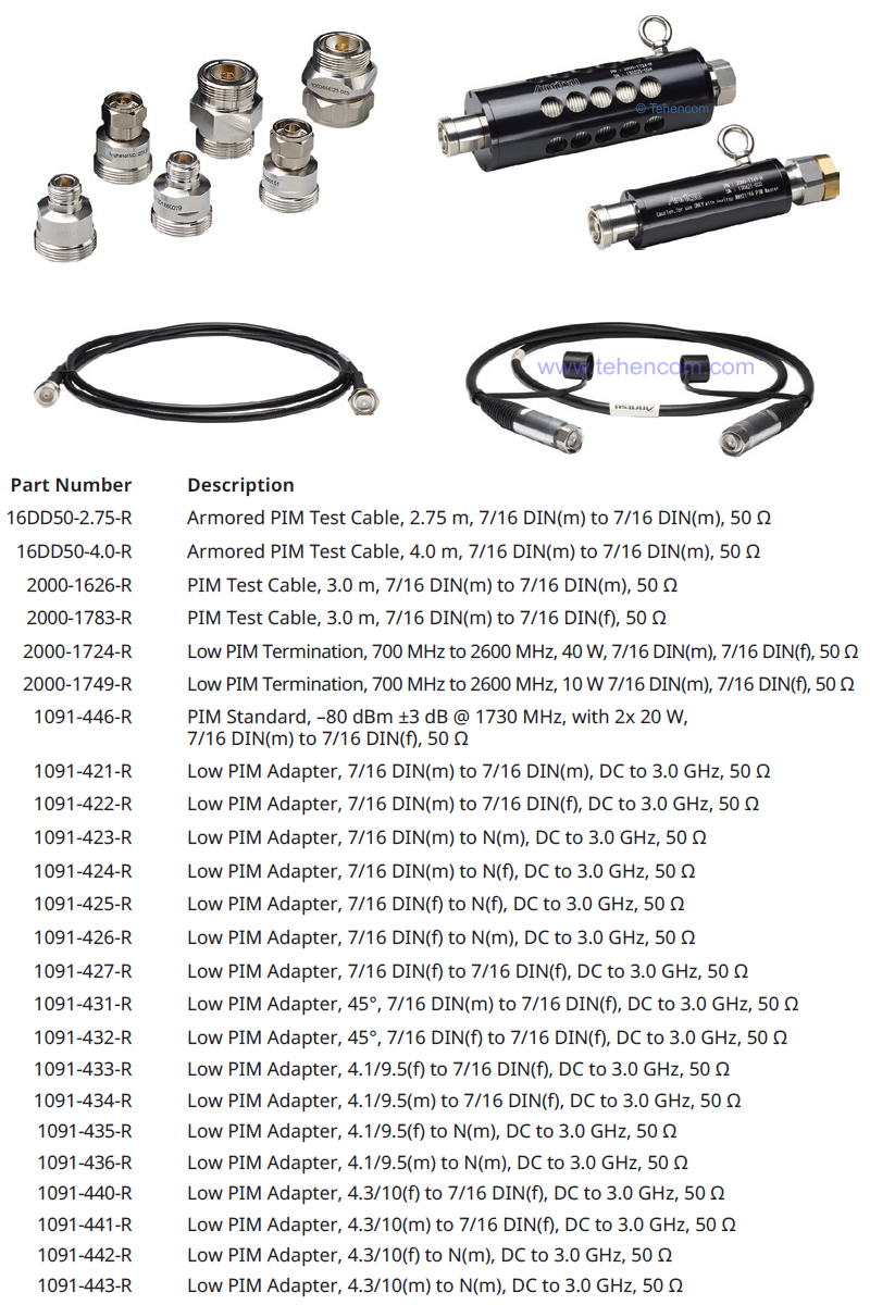
There are many other useful accessories you may need when looking for PIM sources with the Anritsu MW82119B. The main of these accessories with model names (part number) are shown in the photo below. For a wider selection, see Documentation.
Documentation
This PDF documentation contains the most comprehensive description of the Anritsu MW82119B PIM Analyzer features, specifications and modes of operation:
Description of Anritsu MW82119B analyzers (in English) (16 pages; 2 MB)
Anritsu MW82119B Analyzer Specifications (English) (18 pages; 1 MB)
Anritsu MW82119B Analyzers User Manual (English) (168 pages; 16 MB)
Anritsu MW82119B Measurement Software Description (English) (126 pages; 7 MB)
And here you can find our tips and other useful information on this topic:
A Brief Overview of All Series of Anritsu RF Measuring Instruments
An overview of all series of Anritsu handheld RF analyzers
Models and Options of Anritsu Portable Radio Meters
How to buy equipment cheaper - discounts, special prices, demo and used devices
To simplify the process of choosing an analyzer for mobile communication systems, you can use our experience and recommendations. For this it's simple call us or write to us at Email and we will be happy to answer your questions.