Calibrating the vector network analyzer
Brief introduction
Everyone who works with vector network analyzers knows that before starting measurements, network analyzer needs to be calibrated. Calibration accuracy directly affects the accuracy of all subsequent measurements of a vector network analyzer (VNA), so it must be done correctly and accurately.
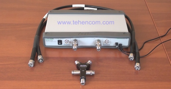
Proper calibration minimizes errors (uncertainty) of the entire measurement system, which, in addition to the analyzer itself, usually includes two phase-stable cables and, in some cases, adapters. Also during calibration, the location of the reference plane is determined, which will be used for all phase measurements. This page details the different calibration methods and shows an example of calibrating an Anritsu MS46122A VNA using the SOLT method.
General Information on Calibration Types of Vector Network Analyzers
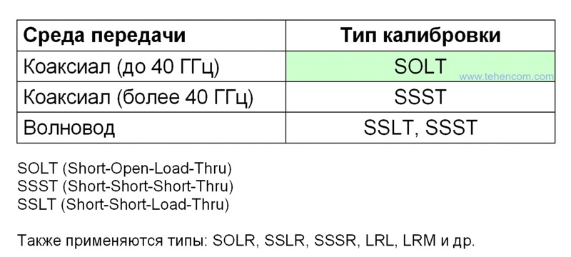
VNA calibration is not a simple and responsible procedure, which depends on the frequency range, transmission medium (coaxial or waveguide), connectors installed on the measurement object and other factors. In total, there are about a dozen different types of calibration. The most common are: SOLT, SSLT and SSST. Moreover, calibrations of the SSLT and SSST types are usually used in waveguide paths. In coaxial paths at frequencies above 40 GHz, the SSST calibration type is most often used, and in the most popular range up to 40 GHz typically use SOLT type calibration. SOLT is an abbreviation for four English words that stand for: Short circuit (Short) - Gap (Open) - Consistent load (Load) and Direct connection (Thru).
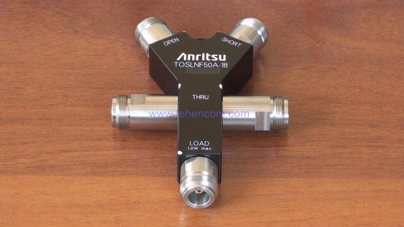
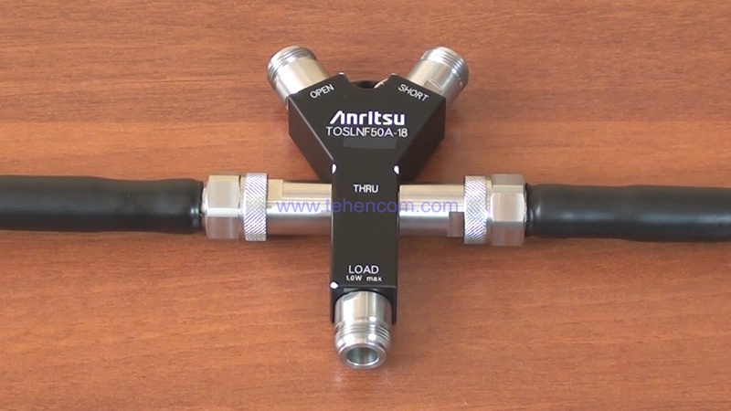
For SOLT calibration a set of precise measures is needed, which are available as separate units or as combined devices, such as the Anritsu TOSLNF50A-18 calibration element shown in this photo, with N-type connectors and a frequency range of up to 18 GHz. It is very important that the connector types of the calibration loads exactly match the connector types installed on the measurement object. For example, if you plan to measure filter parameters with N (female) connectors, then you need to calibrate the analyzer using loads with the same connector.
Preparing for SOLT Calibration
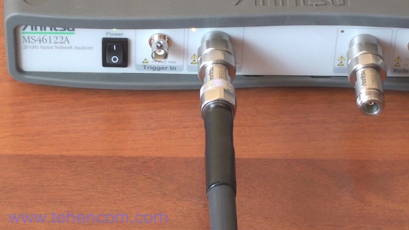
We will demonstrate the calibration process using the example of a compact vector network analyzer Anritsu MS46122A-020 with a frequency range from 1 MHz to 20 GHz. The analyzer is controlled using the Anritsu ShockLine computer program, which controls the operation of the instrument via the USB interface. To connect the analyzer to the measured device, two high-quality phase-stable Anritsu 15NN50-1.0B cables with a frequency range of 18 GHz are used. The Anritsu TOSLNF50A-18 calibration element is also up to 18 GHz, it is specially designed for calibrating network analyzers using the SOLT method and contains four precision measures: Short circuit, Open, Terminated load and Direct connection.
Before Calibration you need to turn on and warm up the device in accordance with the manufacturer's recommendations. To reduce the subsequent temperature drift, it is necessary that the device has already entered the operating mode at the time of calibration. During warm-up, prepare everything you need to take measurements. Make sure that the connectors of all connected devices are not damaged and free of dirt and dust.
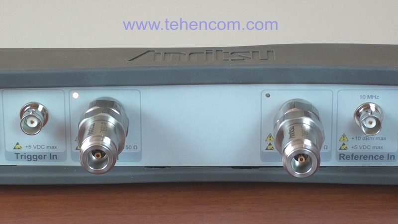
When connecting cables and adapters to each other make sure that the central contacts of the connectors do not rotate relative to each other. Turn the connecting nuts, not the connectors themselves. If you do not follow this rule, then the central contacts very quickly fail due to mutual friction. Also avoid over-tightening the connectors. Do not use regular wrenches to tighten. Carefully connect everything with your hands or use a special wrench with a normalized tightening torque. Such keys are available for common types of connectors: N, K and others.
Performing an Anritsu MS46122A-020 analyzer calibration using the SOLT method
The screenshot below shows the main window of the Anritsu ShockLine software, which is used to control the operation of the Anritsu MS46122A Vector Network Analyzer. Before starting calibration it is recommended to reset the program settings using the preset button. After resetting the settings to the initial state, it is necessary to set the initial and final frequency of the range in which we will calibrate, as well as the number of measurement points. In this example, we will calibrate the instrument from 1 MHz to 18 GHz with 1001 points.
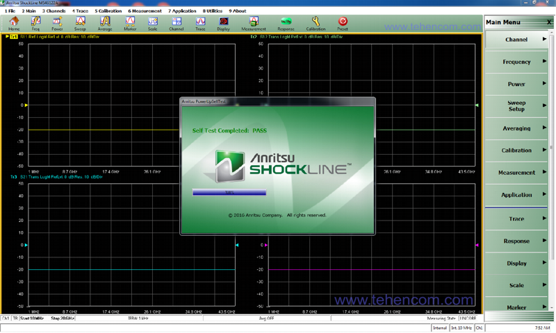
In principle, the frequency range and the number of calibration points will depend on your needs. If during the working day you plan to carry out different measurements at different frequencies, then it makes sense to calibrate over the entire range with the maximum number of points, although this calibration takes longer. If you measure in a small and previously known frequency range, you can calibrate the analyzer in this range with a small number of points. 1000 points will be enough for most tasks. This calibration is much faster, but for measurements at frequencies outside this range, the calibration will have to be done again.
To perform calibration it is necessary to make seven connections and carry out seven measurements parameters of reference standards in the following sequence:
1. Go into the calibration of port 1.
2. Connect the Open element (break) to the cable of port 1. Press the Open button.
3. We connect the Short element to the cable of port 1 (short circuit). Press the Short button.
4. We connect the Load element (matched load) to the cable of port 1. Click the Load button.
5. We go into the calibration of port 2.
6. Connect the Open element (break) to the port 2 cable. Press the Open button.
7. Connect the Short element to the port 2 cable. Press the Short button.
8. Connect the Load element (matched load) to the port 2 cable. Click the Load button.
9. Connect and measure Direct connection.
10. In the window that appears, click OK so that the program performs all the calculations.
After completing these ten points, you must click the Done button in the program. The calibration status will change to ON and a green CORR indicator will appear at the bottom of the window, indicating that the calibration data is being used and all measurements are correct. The calibration element can then be removed.
After performing this calibration, You can measure with maximum accuracy parameters of any devices: filters, attenuators, amplifiers, adapters, etc. Please note that the measurement object must be connected directly to the ends of the phase-stable cables to which the calibration element was connected. If you use any adapter or additional cable for connection, then all its parameters (amplitude and phase) will be added to the parameters of the measurement object. If you still need to use an optional adapter, there is a special procedure to avoid its influence on the measurement results.
Video of a complete 2-port SOLT calibration of VNAs
This video shows in detail how to calibrate a VNA using the procedure above. The calibration process is demonstrated using the Anritsu MS46122A compact vector network analyzer with a frequency range of 1 MHz to 20 GHz. Seven connections and measurements of the parameters of the reference standards are shown, as well as all the necessary actions in the Anritsu ShockLine control program.
Additional information on this topic
We have deliberately not overwhelmed this article with the technical details of performing the various types of vector network analyzer (VNA) calibrations that depend on the frequency range and transmission medium (coax, waveguide, microstrip, etc.). You can read all this in detail in the section on basic theory of analysis of the parameters of electrical circuits. If you are a beginner, then for general information on the ACV, see the article: what is vector network analyzer. Different models of modern VNAs are assembled here, and a guide to choosing the accessories necessary for their operation is located here.
If you need detailed pricing information or technical advice on choosing the best analyzer for your application, just call us or write to us at E-mail and we will be happy to answer your questions.