The principle of operation of an optical reflectometer (OTDR)
Brief introduction
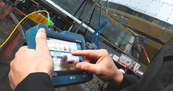
If you work with optical networks, then you have probably heard about an optical reflectometer (in English it is called OTDR), and, perhaps, even performed real measurements with it. At present, an optical reflectometer is the main instrument that is actively used in the construction and operation of any fiber-optic information transmission networks. Why are reflectometers so massively used? Because they allow not only to detect a problem in an optical fiber, but also locate exactly, where this problem is located with an indication of the distance to it in meters.
In order to effectively apply an optical reflectometer in practice, it is necessary to understand the principle of its operation. How does an optical reflectometer work? What components does it consist of? What happens during a measurement? We will consider the answers to these questions in detail in this article. In addition, we will talk about the important aspects of using optical reflectometers in real-world measurements.
Construction of a typical optical reflectometer
Before we begin to understand what is inside the reflectometer, let's see what he has outside. The photo below shows a series optical reflectometer Anritsu MT9083x2, which is structurally very similar to most modern reflectometers. The lightweight portable case contains: a powerful microprocessor, a high-resolution color screen, a rechargeable battery for long-term autonomous operation, and, in fact, the reflectometer itself, the connectors of which are located on the upper part of the case under protective plastic covers.
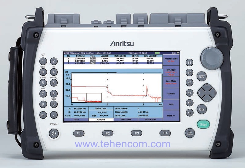
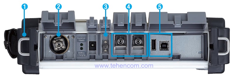
The photo below shows the top of the Anritsu MT9083x2 OTDR with all protective covers open. The numbers indicate: 1 – side elements of the case for protection against impacts, 2 – optical power meter connector, 3 – visible (red) light source for visually finding entangled or damaged fibers, 4 – two separate optical reflectometer connectors (one for single-mode fibers, the second for multimode), 5 – USB interfaces.
Almost all good reflectometers contain all these elements, but now we only interested in optical reflectometer connectors (number 4 in the photo). More precisely, only one connector – for connecting single-mode fibers. Next, we will consider in detail the principle of operation and the internal structure of a single-mode reflectometer. Two other types of reflectometers: for multimode fibers and for measurements on active fiber are built on exactly the same principle.
The principle of operation of an optical reflectometer
An optical reflectometer works on the principle of a radar – it sends a short powerful pulse of light into the fiber and immediately begins to measure all the reflections that occur when this pulse moves along the fiber. As soon as the probing light pulse reaches any inhomogeneity in the fiber, for example, welding, connector or damage, part of the light is immediately reflected from this place and begins to move along the fiber in the opposite direction – towards the reflectometer – where it is recorded by the photodetector. But the probing pulse itself, although slightly weakened, continues its movement along the fiber, successively reflecting from all inhomogeneities encountered on its way, until it reaches the end of the fiber or the place of its complete break.
Inside the optical reflectometer there are three main elements (laser, splitter and receiver) that provide measurements of the parameters of the optical fiber and on which the characteristics of the reflectometer and its accuracy depend. The interaction of the main elements of the reflectometer is shown in this diagram.

The first element is a laser LED that generates short probing pulses of the required duration (usually from 5 ns to 20 µs). For each wavelength, there is a separate laser LED inside the reflectometer. For example, if the reflectometer operates at two wavelengths: 1310 nm and 1550 nm, then two laser LEDs are installed in it.
The second element is an optical splitter, which transmits laser radiation into the optical fiber, but does not allow it to enter the receiver. The splitter also ensures the passage of the light reflected in the fiber to the receiver of optical radiation for its registration and measurement.
The third element is a sensitive photodetector that accurately measures the levels and time delays of all reflections that appear as the probing light pulse travels along the fiber. The two most important parameters of an optical reflectometer depend on the quality of the receiver: dynamic range and dead zone. In addition, the quality of the receiver directly affects the accuracy of the measurement itself.
All three elements are included in this short tutorial video illustrating how the OTDR works through animation. The video shows how the measuring pulses are formed using a laser LED, how they enter the main fiber using an optical splitter, and how the reverse pulses reflected from various fiber inhomogeneities return to the reflectometer photodetector.
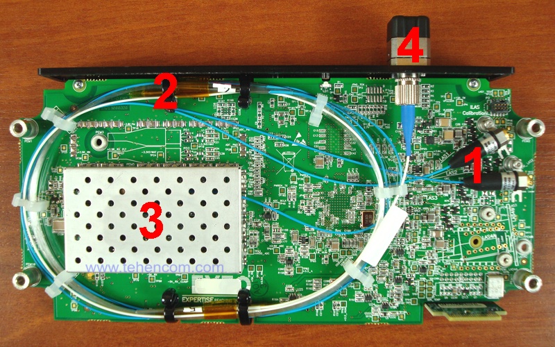
The photo below shows how it all looks in reality. Here is the main board of a modern single-mode optical reflectometer, which operates at wavelengths of 1310 nm and 1550 nm. In this photo, the numbers indicate the three main elements of the reflectometer (lasers, splitter and receiver), as well as its input connector, to which the measured fiber is connected.
Please note that the measurement of all reflections from one probing light pulse will not allow you to build a complete reflectogram. The power of a single pulse is very small, and when measuring its reflections, a large amount of random noise is recorded. In order to minimize the effect of noise and obtain a clean trace, it is necessary to take a measurement for some time, usually from 10 to 20 seconds. During this time, the optical reflectometer manages to send thousands of probing light pulses into the fiber and measure the reflection of each of them. After that, it performs averaging, analysis and display of the results in the form of a trace graph and an event table, which is located below the graph.
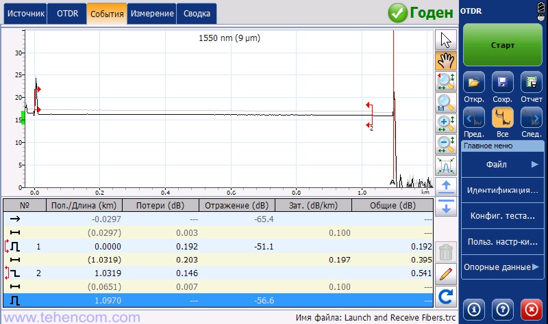
For example, this screenshot shows the result of measuring the parameters of a single-mode fiber with a length of 1.0970 km, which was performed using a compact reflectometer EXFO MaxTester 720B. This fiber was found to have a bad splice with a loss of 0.146 dB located at a distance of 1.0319 km from the beginning of the tested fiber. It is marked on the reflectogram as event #2.
What is important to know when you are just getting started with an optical reflectometer
In the previous section, we figured out how an optical reflectometer works. It is clear that for the sake of simplicity of explanation, we have not considered minor and insignificant details. The main purpose of this article is to give a good, basic understanding of how an optical reflectometer works and to talk about the most important things so that you can successfully start using this device.
There are two things to keep in mind when working with an optical reflectometer.:
1. Ordinary optical reflectometer cannot be connected to an active line! The photodetector of a reflectometer is a very sensitive device that is capable of measuring the minimum levels of light flux, and if powerful radiation enters it, for example, from a trunk transmitter, the reflectometer will go into protective mode or simply burn out. The exception is special reflectometers designed for testing active fibers, for example, the model EXFO MAX-730C-SM8. These reflectometers have a separate connector with an operating wavelength of 1625 nm or 1650 nm and a built-in filter that cuts off other wavelengths. If you do not know for sure whether there is radiation in the connected fiber, then first check this using any optical power meter.
2. The OTDR input connector is very easy to damage., but then it is difficult and expensive to repair. The central part of the connector is a ceramic cylinder with a diameter of 2.5 mm. In the center of this cylinder is the core of the optical fiber, through which the radiation passes. The core diameter of a single-mode fiber is 9 µm (less than one hundredth of a millimeter). Any dirt or micro-scratch in the central part of the connector can damage the device. The reflectometer itself will work, but the light will no longer be able to pass normally into the fiber. Dirt can still be cleaned, although it is not easy, but if scratches appear, you will have to carry out repairs. To ensure that the OTDR input connector is always in top condition, clean any patch cord you are going to connect to it right before connecting it. Besides, you can connect a small patch cord with an adapter socket at the second end to the reflectometer once and never disconnect it again. With this method, in the process of work, the second end of the patch cord will be scratched, and the reflectometer connector will remain intact.
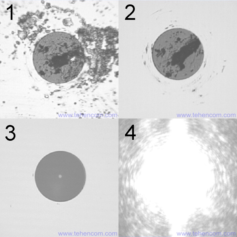
The illustration below shows four photographs of different optical connectors. These photographs were taken with a special optical microscope with a magnification of 400 times. Photo 1 shows the input connector of a single-mode reflectometer, which was sent for repair to our service center. At first glance, the connector is just very dirty and can be cleaned. Photo 2 shows the appearance of the same connector after thorough cleaning. As you can see, the dirt was removed, but under it were scratches and a few large scuffs. To restore the operation of this reflectometer, I had to completely replace its input connector. Photo 3 shows a new connector immediately after replacement – clean and without scratches. In the very center of the connector in photo 3, a brighter point is clearly visible – this is the core of a single-mode fiber, through which the optical signal must pass. Its diameter is only 9 microns (1 micron = 0.001 mm). And in photo 4, we decided to show what it looks like, when viewed with a microscope, an active fiber to which, as you already know, a reflectometer cannot be connected.
Setting up an optical reflectometer for measurements
Now let's move on to measurements. An optical reflectometer is connected to the fiber under test using an adapter patch cord (usually three meters) or a compensation coil (300 to 500 meters long). What to use: short patch cord or long spool? It depends on your goals: if you just want to find a fault in the fiber, then you can use a short patch cord, and if you plan to get a certificate for optical fibers, you will have to measure with two coils (one at each end of the fiber), besides measuring each fiber will need to be done in two directions.
It is important that the fiber type of the patch cord or spool matches the fiber being tested. For example, if you are testing single-mode fiber at 1310 nm and 1550 nm, then you should use single-mode patch cords or spools with standard G.652 fiber. If you are testing at 850 nm and 1300 nm multimode fiber with a 50 µm core, then the connecting patch cords or coils must also be of the same type of multimode fiber with a 50 µm core.
When everything is connected correctly, you can start measuring. Before starting the first measurement, you must select the desired wavelengths and correctly set the initial settings of the reflectometer: measured distance, probing pulse duration and total measurement time at one wavelength. The photo below shows how these settings look on the reflectometer screen. EXFO MaxTester 720B. Any other reflectometer, regardless of manufacturer and specific model, will also have these settings. They may look different or be hidden in the menu, but wavelengths, distance, pulse and duration are basic parameters and can always be set in any reflectometer.

Let's take a closer look at each of these four basic optical reflectometer settings.
Wavelengths. This is the simplest setting. In 99% of cases, single mode is measured at wavelengths of 1310 and 1550 nm, and multimode at wavelengths of 850 and 1300 nm. The exceptions are reflectometers for PON with three wavelengths 1310/1490/1550 nm, as well as improved search for macrobends at wavelengths of 1310/1625 nm and measurements on active fibers (usually 1625 nm is used, less often 1650 nm), but in practice such reflectometers are found infrequently. So, if you are measuring single mode fibers, then set 1310 and 1550 nm, and if multimode, then 850 and 1300 nm. True, if you just need to determine the length of the fiber or the location of the break, then only one wavelength can be selected for acceleration.
Measured distance. The main rule to follow when setting the distance is that the end of the optical line must always be visible on the reflectogram. If you have a line of 500 meters, set the distance to 1.25 km. If you have a 4 km line, set the distance to 5 km. This is important for automatic processing of the reflectogram by the instrument itself. If the reflectometer does not see the end of the optical fiber, it will be difficult for it to calculate the position of light reflections in the fiber and false events (for example, phantom peaks) may appear on the reflectogram. Therefore, always measure the full length of the fiber, plus a small margin for distance. If the exact length of the fiber is not known, take a quick measurement at the same wavelength and over a long distance to find out the length of the fiber.
Duration of probing pulses. The pulse duration directly affects the dynamic range and dead zone of the reflectometer. The smaller the impulse, the better the dead zone, and hence the ability of the reflectometer to distinguish closely spaced events. But at small pulses (5 - 10 ns), the optical reflectometer has a minimum dynamic range, which means that only short lines can be reliably measured. Therefore, the pulse duration that you will use for measurement directly depends on the quality of the reflectometer, the length of the optical fiber and the total attenuation in this fiber. For short lines (up to 2-3 km), set the pulse to 10 or 30 ns. For lines of medium length (up to 20-30 km), set the pulse from 100 to 500 ns. For extended highways (more than 50 km), use powerful pulses with a duration of 1 µs or more. Experiment with this setting. It is necessary that the reflectogram that you receive does not contain noise and all events are clearly visible on it.
A separate issue is the choice of pulse duration for passive optical networks. To measure only the first splitter on the subscriber side, pulses of 50 ns or 100 ns are suitable. And for end-to-end measurement of the entire fiber (from the subscriber to the OLT), containing two or three splitters, it is necessary to use powerful pulses of 500 ns or 1000 ns. See details here: reflectometers for PON.
Total measurement time. The longer the measurement time, the more accurate the trace will be and the less random noise it will have. All characteristics of the reflectometer itself, specified in its documentation, are checked with a measurement time of 180 seconds for each wavelength. When checking or calibrating an optical reflectometer, a measurement time of 180 seconds is also used. But in practice, in order to quickly get the job done, in most cases, set the measurement time in the range from 10 to 30 seconds for each wavelength. If there are many fibers (several hundreds on one object), they are short (up to 2-3 km) and you have a high-quality reflectometer, then you can set the measurement duration to 10 seconds.
Taking measurements with an optical reflectometer
Now let's move on to measurements. When you have configured all the initial settings for the optical reflectometer, you can start the measurement itself. During operation, the OTDR will constantly update the trace on the screen, averaging many individual tests. When the measurement is finished, processing will start. It usually takes 1 to 5 seconds. At the end of processing, a table of events will appear under the trace, which will indicate the distance to each event, the losses that it introduces and the level of its reflection, as well as other useful data. This reflectogram can be saved to the instrument's memory for further processing or used immediately to find problem areas in the optical fiber and correct them - overcooking, cleaning connectors, straightening macrobends, etc.
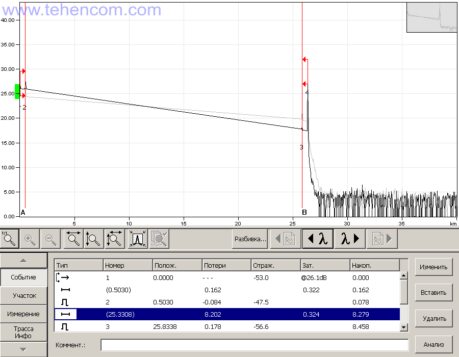
As an example, this photo shows the trace and table of events for a 25 km single-mode fiber coil with two 500-meter compensation coils, one of which was connected between the reflectometer and the coil, and the second at the far end of the coil. The trace consists of two separate graphs: a gray graph with a smaller slope for a wavelength of 1550 nm and a black graph (highlighted as active) for a wavelength of 1310 nm. On the reflectogram, the bay itself starts at event 2 and ends at event 3. In the table of events, located immediately below the trace, the blue marker is placed on the line with the measured characteristics of this bay: the actual fiber length is 25,330 meters, the total loss in the fiber of the bay is 8.2 dB , attenuation 0.324 dB/km.
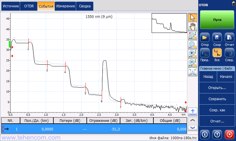
And this is what the reflectogram looks like PON network simulator, containing three splitters: 2 pcs. with a division factor of 1x8 and 1 pc. with a division factor of 1x2. The reflectogram was measured with an inactive fiber at two wavelengths (1310 nm and 1550 nm). Measurements were taken from the subscriber connection side using an EXFO MaxTester 730C reflectometer. The test pulse duration was 1000 ns, and to reduce noise, a long averaging time of 180 seconds was set.
On this trace, the first 1x8 divider is located at a distance of 500 meters and is marked as event No. 2. The second divider 1x8 is located at a distance of just over 1.5 km (event No. 4). The third 1x2 divider (event #5) is located at a distance of about 2.1 km. For more information about PON testing, see this article.
Additional information on this topic
This page describes in detail the principle of operation of an optical reflectometer, describes how it works, provides detailed recommendations on choosing the initial settings and taking measurements. To better navigate the models of modern optical reflectometers and their capabilities, see the main page individual series of optical reflectometers. See also special article dedicated to the comparison of five models of optical reflectometers for measuring passive optical networks in the construction process.
If you need detailed pricing information or technical advice on choosing the best OTDR for your application, just call us or write to us at E-mail and we will be happy to answer your questions.