Types of devices according to the method of alignment (alignment) of optical fibers: core convergence (PAS), active V-grooves, jacket convergence
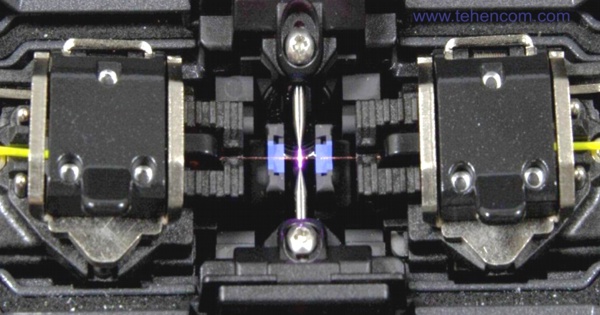
Brief introduction
In this article, we will take a closer look at one of the main characteristics of the fiber optic splicer - optical fiber alignment method (also use the terms: convergence or alignment of fibers). Why is this feature so important? Because it determines the class of the welding machine and significantly affects its cost and the quality of the resulting welded joint.
The vast majority of modern models from any manufacturer use one of three fiber alignment methods: core alignment (PAS technology), simpler moving V-groove alignment and the simplest method is bringing the fibers along the sheath with fixed V-grooves. Previously, several more alignment methods were used (for example, LID, etc.), but they are practically not used in modern models. So, let's look into this in detail.
Optical fiber recognition system
In order to align and splice the fibers, the machine needs to acquire an image of them. After all it is from the image that the device determines types of fibers, combines them, adjusts the parameters of the arc during welding and evaluates the loss of the resulting welded joint.
The figure below shows a simplified diagram of the optical fiber recognition system of most modern devices (it is also called the "Optical path of the device"). Understand how it functions, as you will need it to understand the differences between machines, as well as for any practical fiber splicing job.
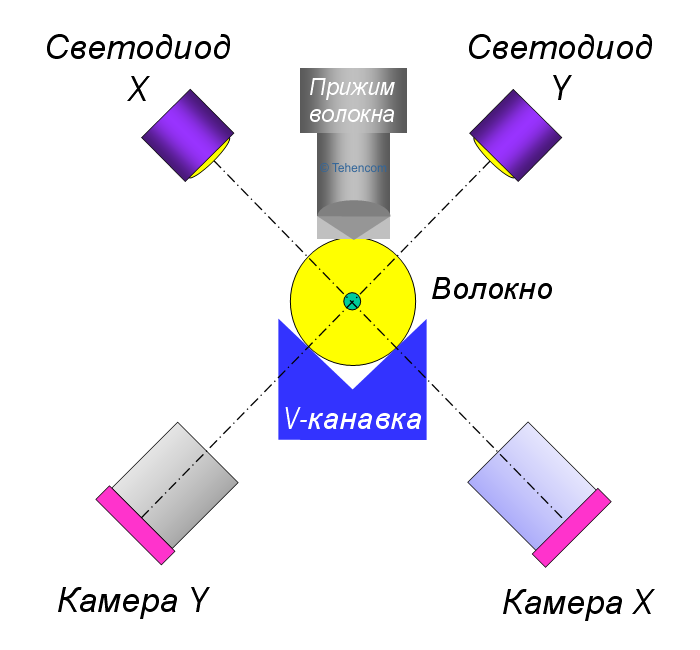
Two fibers (left and right) are placed in the V-shaped grooves and are fixed from above with two clamps. The fibers are illuminated by two LEDs located above the fibers at an angle of 90°. Light, passing through the fibers, forms their image on two cameras (X and Y), which are located below the level of the fibers and are also oriented at an angle of 90°. By analyzing both images, the device obtains all the information it needs to work. This photo shows what it looks like in reality on the screen of the Fujikura 80S welding machine. At the top of the screen is an image of the left and right fibers obtained by the X-camera, and at the bottom of the screen is an image of the same fibers in a perpendicular projection obtained by the Y-camera.
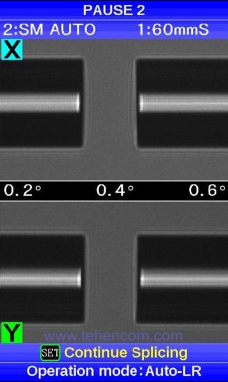
This method of fiber imaging is used in all devices of the current Fujikura line (models 80S, 62S, 22S, 12S etc.), as well as in many models from other manufacturers. In older models of devices, a more complex method was used, in which the light from the LEDs was first directed to two mirrors and, reflected from them, passed through the fibers. Regardless of how the fibers are illuminated (directly by LEDs or through mirrors), the cameras always form two images, which are two projections of the fibers located at an angle of 90 °. And now that we have figured out how the apparatus "sees" the fibers, let's move on to considering three methods by which the fibers are brought together.
Bringing fibers into sheath with fixed V-grooves
The first and easiest method is cladding of optical fibers with fixed V-grooves. This method is used in inexpensive and compact devices designed for welding access networks, PON, FTTx and SCS. Typical representative: model Fujikura 12S. In such devices, the fibers are placed in two fixed V-shaped grooves, the geometric dimensions and shape of which provide a very precise alignment of the fibers in relation to each other. This photo shows two optical fibers in the blue V-grooves of the Fujikura 12S.
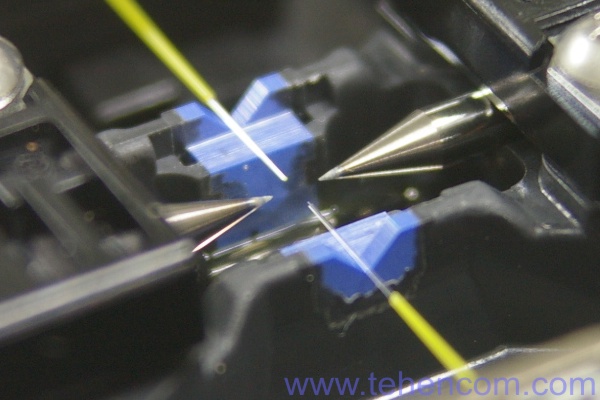
During welding, the ends of the fibers are melted by an arc discharge and brought together into one piece. When the arc of the apparatus is turned off, the molten glass cools down and, due to the forces of surface tension, additional self-alignment of the fibers occurs.
The main advantage of devices with fixed V-groove adjustment is simplicity of design. In such devices, only two motors are used, which simply bring the fibers together to the welding point. Since the design is not complicated, the devices have compact dimensions, low cost and increased reliability. The typical splice loss of two single-mode fibers is 0.05 dB, which is completely suitable for building any access network.
However, the simplicity of the design has a downside. Since the V-grooves are fixed, their contamination disturbs the alignment of the fibers. Therefore, such devices must be kept clean and periodically wipe the V-grooves and fiber clamps with alcohol.
The second feature: if the optical fibers are bent (for example, due to long-term storage in a bent state) or if the fibers are of poor quality and their core is not quite in the center (there is an eccentricity of the core with respect to the cladding), then splice losses will increase, so how the machine will not be able to trim one fiber in relation to another.
The third feature: the cameras of such devices have a fixed focus (for more details about the focusing system, see below). Consequently, the accuracy of estimating the losses that occurred during welding is not as high as in devices with variable camera focus.
Fiber convergence with active (moving) V-grooves
Such devices also have a fixed focal length, but the V-shaped grooves can move in two planes. This means that the devices are more resistant to contamination and non-ideal geometric dimensions of the fibers themselves. In the English documentation, this alignment method is called Active V-Groove.
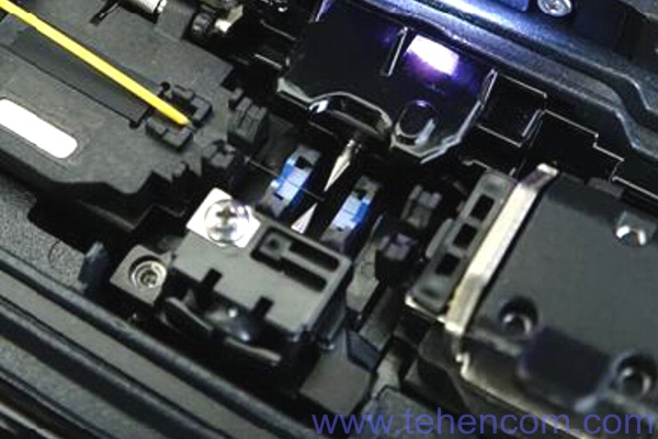
The design of the devices is more complicated than that of the previous category, and the cost is about 1.5 times higher. Two additional motors are used to move the V-grooves, slightly increasing the size. In total, 4 motors are used in the fiber convergence system of such devices: two for moving the fibers towards each other and two for bringing the fibers in the X and Y planes. A typical representative of this category: the model Fujikura 22S. This photo shows the active V-grooves of this model (two elements in blue in the center of the photo).
Active (moving) V-groove convergence devices are ideal for any city-wide fiber optic network. Typical splice loss of two single mode fibers is only 0.03 dB. These devices are intermediate between simple models with fixed grooves and top models with accurate core convergence.
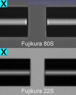
Their main difference from top models, such as Fujikura 80S and Fujikura 62S, this is the fixed focal length of the cameras. The cameras "look" at the center of the fiber, which is why the image of the core of a single-mode fiber is thin and not as detailed as in older models. Therefore, the accuracy of fiber convergence and the accuracy of estimating the losses that result from welding are not so high.
You can clearly see the difference in the photo below. The top of this photo shows an image of a pair of single-mode fibers taken with the older model Fujikura 80S, and the bottom of the photo shows an image of the same pair of single-mode fibers taken with a Fujikura 22S fixed-focal camera model. Notice how the fibers at the top of the photo are sharper and more detailed.
In general, devices that bring fibers together using active (moving) V-grooves represent an excellent compromise between cost and performance. But if you need maximum performance, then choose one of the welding machines with precise core alignment and variable focal length (PAS technology). Next, we will talk about them in detail.
Precise convergence of fibers along the core (PAS technology)
The most advanced from a technical point of view are devices that implement the technology of precise convergence of optical fibers along the core using their brightness profile PAS (short for Profile Alignment System). These devices use two additional motors to move the X and Y cameras, which allows you to change the plane of their focus. In total, 6 motors are used in the fiber convergence system of such devices: two for moving the fibers towards each other, two for bringing the fibers together in the X and Y planes, and two for changing the focal length of the X and Y cameras.
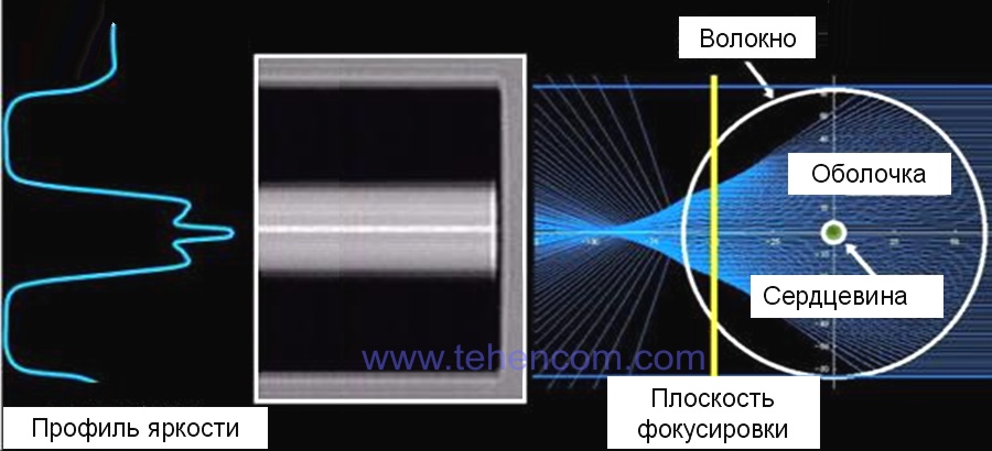
The use of the brightness profile of optical fibers for their mutual alignment is well illustrated in this figure. Its right side shows a cross-section of a single-mode fiber with a core in the center. Parallel beams of light come from the LED and, passing through the fiber, are refracted, because glass fiber has the properties of a lens. The yellow vertical line in the figure is the focusing plane of the device's video camera. As you can see, the plane of focus does not pass through the core of the fiber, as in simpler models, but closer to the edge of the fiber. This gives an enlarged image of the core and a thin strip of increased brightness, which appears in the very center due to the superposition of light rays. The microprocessor of the welding machine, analyzing such an image, can very accurately determine the position of the fiber core, as well as its other characteristics, for example, the type of fiber: single-mode, multimode, dispersion-shifted, insensitive to bends, etc.
If you are splicing not only single-mode (G.652) and multimode (G.651) fibers, but also other types, such as bend-insensitive (G.657) or trunk (G.653 and G.655), then it is advisable to use splicing devices that can analyze the brightness profile. This is due to two reasons. First reason - this is the highest quality welding. For Japanese devices, typical losses at the splice of two single-mode fibers are normalized at the level of 0.02 dB, but in reality about 0.01 dB. Such welding cannot even be seen with a reflectometer. The second reason - Each type of fiber has a unique brightness profile. Brightness profiles for fibers of all standards are stored in the memory of the machine and in the process of fiber recognition, the machine can accurately determine their type and select the optimal splicing program.
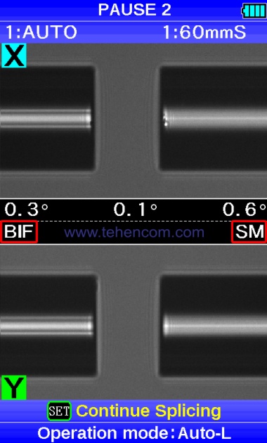
This photo shows the screen of a Fujikura 80S fusion splicer, in which two different fibers are installed: on the left, bend-insensitive (G.657), and on the right, a conventional single-mode. As you can see, the images of the fibers are different (there are horizontal stripes on the left fiber) and the device correctly determined their types (BIF and SM) from the details of these images.
The whole process of accurately bringing the fibers to the core and splicing them in the "Full Automatic" mode is shown in this short video. The first part of the video (17 seconds) is played at full speed, and the second part shows the same welding, but with 5 times slowdown and step by step comments so you can have a good look at all the steps: 1 - cleaning arc, 2 - preliminary convergence of the fibers, 3 - change of focus to analyze the brightness profile of the fibers, 4 - determination of the type of fibers, 5 - accurate reduction of fibers to fractions of a micrometer (almost not noticeable), 6 - main arc, 7 - loss estimation.
In theory, precise alignment of fibers along the core using PAS technology looks simple. But it is not for nothing that welding machines of this category are considered the most advanced and expensive. Look at these photos, they clearly show the technical complexity of the implementation. The disassembled device is shown on the left. Fujikura FSM-60S, which is the forerunner of the modern flagship Fujikura 80S. And on the right, its upper part is in an inverted position. On the right photo, 6 motors are highlighted, which are responsible for the movement of the fibers towards each other (1, 2), the alignment of the fibers in the X and Y planes (3, 4) and for changing the focal length of the two cameras of the apparatus (5, 6).
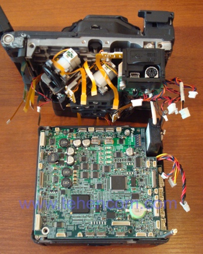
Microprocessor board (bottom) and Fujikura FSM-60S focusing and fiber convergence module |
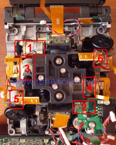
Fujikura FSM-60S focusing and fiber convergence module |
Now that we have examined in detail the features and differences of the three main methods for aligning optical fibers, let's summarize this information in order to have a good understanding of which type of device is best suited for a particular task.
Summarizing information by type of apparatus
Devices with precise core alignment (according to PAS technology) are suitable for the construction and maintenance of any type of modern optical networks, both urban and intercity. They quickly and with minimal losses splice any type of fiber: single-mode (G.652), multimode (G.651), bend-insensitive (G.657) and trunk (DSF G.653 and NZDSF G.655). Typical representatives of this category: Fujikura 80S and Fujikura 62S.
Machines with fiber alignment using moving V-grooves they can converge fibers in three planes, but they cannot change the focusing plane of their cameras, so the quality of their welding is slightly lower. These devices are positioned as the optimal solution for any city-wide networks. A typical representative of this category: Fujikura 22S.
Apparatus with fiber alignment on the sheath using fixed V-grooves are the simplest from a technical point of view. They simply precisely bring two fibers to the fusion point. These devices are positioned as the optimal solution for access networks, PON networks, SCS and the like, where the number of splices in one link (from transmitter to receiver) is small (usually less than 10). A typical representative of this category: Fujikura 12S.
Additional information on this topic
This page details the main methods of alignment (alignment) of optical fibers, which are used in modern optical fiber splicers from most manufacturers. This material will help you better understand the design of various devices and the principles of their operation.
To learn more about electrode wear and maximum number of welds, see this article. And to get acquainted with the full list of models of the Japanese company Fujikura, go to the main page splicers for optical fiber.
If you need detailed pricing information or technical advice on choosing the best welding machine for your application, just call us or write to us at E-mail and we will be happy to answer your questions.