Instruments and measurement methods for the development and production of power supplies, inverters and AC/DC, DC/DC, DC/AC, AC/AC converters
Brief introduction
In this article, we will talk about modern instruments and measurement techniques that are used in the development, research and production of secondary power supplies with power from fractions of a watt to hundreds of kilowatts.
The information provided on this page will be useful to engineers working on projects of switching and linear power supplies, inverter converters, voltage stabilizers, uninterruptible power supplies, electric vehicle charging stations, smart motor drives and any other devices that perform power conversion.
For convenience, the entire text is divided into thematic sections:
- input laboratory power supply
- output electronic load
- measurements at the point of connection to the alternating current (AC) network
- measurement of the characteristics of the internal components of the power supply
- measurements at the point of connection to the direct current (DC) network
- measurements between the input and output of the power supply
- checking the electrical safety of the power supply
The instruments and measurement methods described in this article are used when working with secondary power supplies and converters of all types: AC / DC, DC / DC, DC / AC and AC / AC (the abbreviation AC stands for Alternating Current, that is, alternating current, and DC means Direct Current, that is, direct current).
Laboratory power supply input
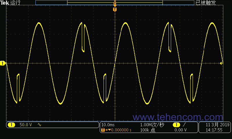
To work with the prototype of the developed power supply, it is necessary to connect to its input laboratory power supply sufficient power with the ability to adjust the voltage. The type of output voltage (DC or AC) depends on the first stage of the power supply being developed. For DC/DC and DC/AC converters you will need a DC power supply, and for AC/DC and AC/AC AC (single-phase or three-phase).
The laboratory power supply at the input of the developed prototype solves the following tasks: amplitude adjustment voltage to test the prototype in the entire operating range, the formation stresses of various forms (ripple, dip, ramp, etc.) to test the stability of the prototype under real-world conditions, and also provides protection prototype from various types of overloads.
As laboratory power supplies direct current can be used: for power up to 600W series ITECH IT6900A, for power up to 3 kW series ITECH IT6700H, for power up to 1.152 MW series ITECH IT6000D/C/B.
As laboratory power supplies alternating current can be used: for power up to 3 kVA series ITECH IT-M7700 (1 phase), for power up to 54 kVA series ITECH IT7600 (1 and 3 phases).
Electronic load output
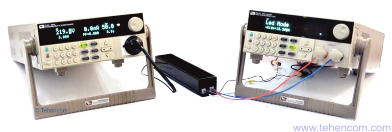
To study the developed prototype of the power source in various operating modes, it is necessary to connect to its output programmable electronic load. The type of electronic load (DC or AC) depends on the last stage of the power supply being developed. For DC/DC and AC/DC converters you will need a DC electronic load, and for DC/AC and AC/AC AC (single-phase or three-phase).
The programmable electronic load at the output of the developed prototype solves the following tasks: power consumption adjustment to test the prototype in the entire working range and form dynamic load (imitation of starting current, sharp change in consumption, short circuit, etc.) to check the stability of the prototype in real conditions. The electronic load can absorb energy in the following modes: constant resistance mode, constant current consumption mode, constant power consumption mode and voltage stabilization mode.
As electronic loads direct current can be used: for power up to 3 kW series ITECH IT8500+, for power up to 45 kW series ITECH IT8900.
As electronic loads alternating current can be used: for power up to 43.2 kVA series ITECH IT8600 (1 and 3 phases).
Development of the main device
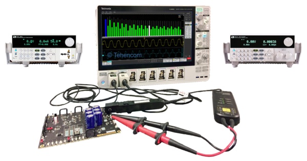
When the first prototype of the power supply is designed and manufactured, the stage of testing its characteristics in various normal and abnormal modes begins with subsequent refinement and optimization. For this, it is most often used digital oscilloscope with a set of differential and current probes.
Some measurements, such as power and power factor, can be made with a conventional two-channel oscilloscope (for example, Tektronix TBS2000B) using built-in mathematical operations on signals. But for a full-fledged study, you need a good multi-channel oscilloscope with a 12-bit ADC (level Tektronix MSO4 or MSO5) and special software that automatically calculates dozens of characteristics important for optimizing the power supply.
Next, we will talk about the main types of measurements carried out during the development and optimization of a prototype power source, as well as the necessary devices, options and accessories for this.
Measurements at the point of connection to the alternating current (AC) mains
The measurements described in this section are made at the point where the AC/DC and AC/AC power supplies are connected to the AC mains. The purpose of these measurements is to ensure that the effect that the power supply under test has on the network is within specified limits.
In addition, the equipment and techniques presented in this section apply to testing DC/AC and AC/AC power supplies at the point they are connected to the alternating current (AC) load to which they supply power.
Most power supplies introduce distortion into the power supply to which they are connected. Linear transformer power supplies are an inductive load and, in addition to active power, they also consume reactive power. Switching power supplies not only load the network with a non-linear load, but also introduce broadband interference into it. Even the highest quality switching power supplies with active power factor correction still introduce distortion that needs to be controlled.
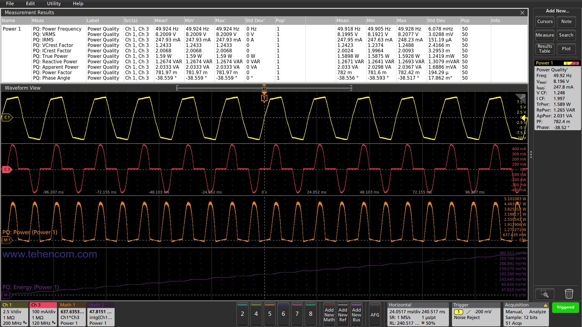
There are several main characteristics that are measured at the point of connection of the power supply to the AC mains: frequency, RMS voltage and current values, active, reactive and full power, Power factor, phase angle and voltage and current crest factors. These parameters are standardized by various standards, such as IEC61000-3-2.
You can use oscilloscopes for measurement Tektronix MDO3 with software option 3-PWR, as well as oscilloscopes of the series MSO4, MSO5 and MSO6 with corresponding software options 4-PWR, 5-PWR and 6-PWR. The MSO4 and MSO5 series are optimal because they contain models for 6 and 8 channels with ADC 12 bits.
For example, in this screenshot of an eight-channel oscilloscope Tektronix MSO58 with the 5-PWR option installed, waveforms and numerical measurements of all the above parameters are shown. At the bottom of the screen is an additional graph of consumed energy in mJ.
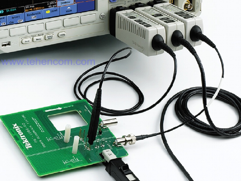
Before carrying out measurements of power supply characteristics with an oscilloscope, it is necessary to zero the offset of differential probes (AutoZero), demagnetize current probes with their offsets set to zero (Degauss + AutoZero) and eliminate the delay between voltage signals and current signals (Deskew).
To eliminate the delay, special devices are usually used (Deskew Pulse Generator and Deskew Fixture), for example, the TEK-DPG generator shown in this photo (powered by the third channel of the oscilloscope) and fixture 067-1686-XX (green board with two current loops).
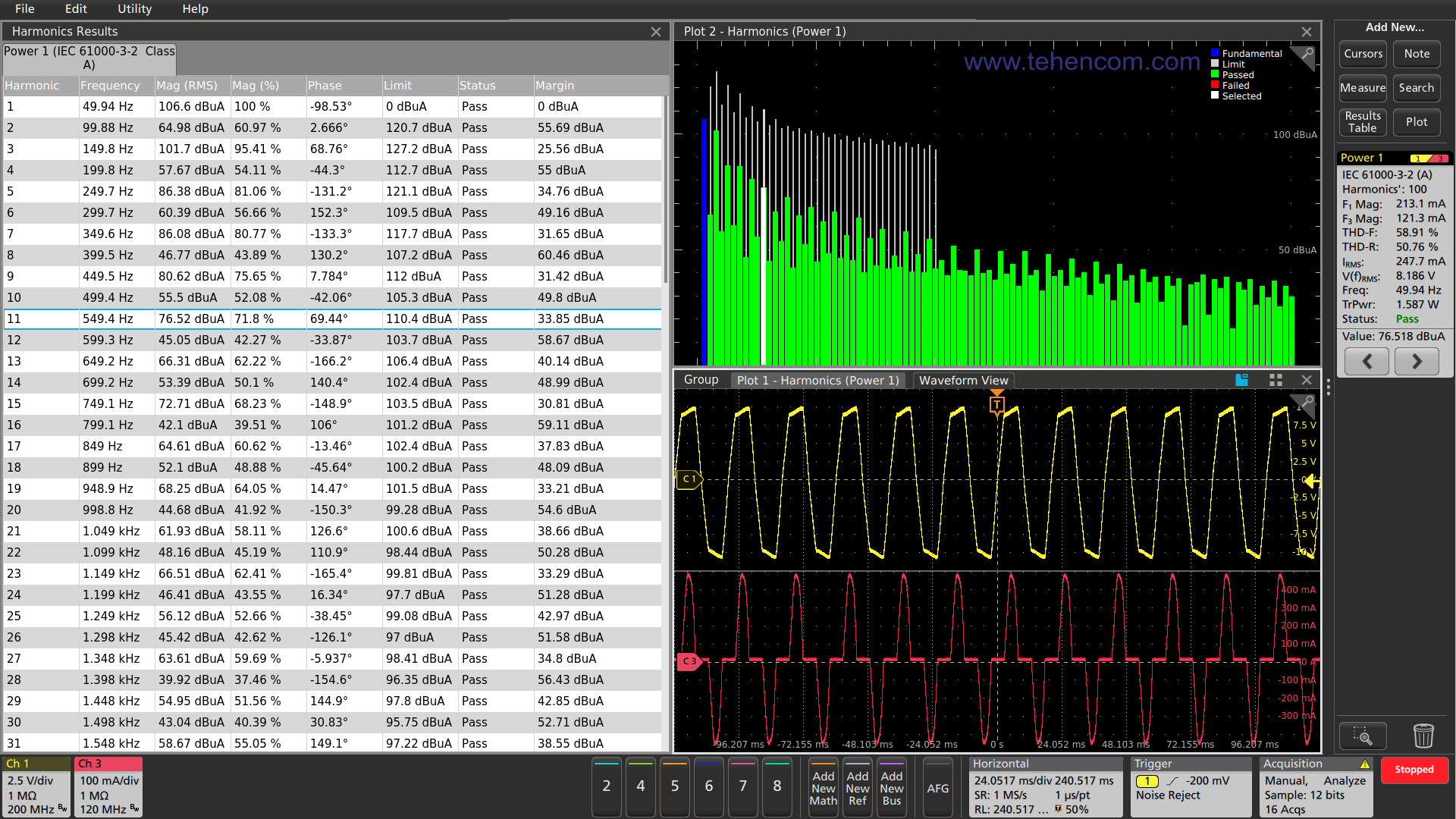
Another type of testing at the point of connection to the AC mains is associated with determining the level of harmonic distortion that the power source under investigation creates in the network. At the same time, they measure individual harmonic levels and general harmonic distortion factor (THD). These measurements are provided by various standards, including IEC61000-3-2, AM 14, MIL-STD-1399 and others.
You can use the Tektronix MDO3 Series oscilloscopes with the 3-PWR software option, and the MSO4, MSO5, and MSO6 series oscilloscopes with the appropriate 4-PWR, 5-PWR, and 6-PWR software options, for measurements. For example, this screenshot of a Tektronix MSO58 oscilloscope with the 5-PWR option installed graphically and tabularly shows the characteristics of one hundred harmonics. Please note that the oscilloscope not only measured the parameters of each harmonic, but also analyzed it to meet the tolerances of the IEC61000-3-2 standard. Test result "Passed" (Status: Pass).
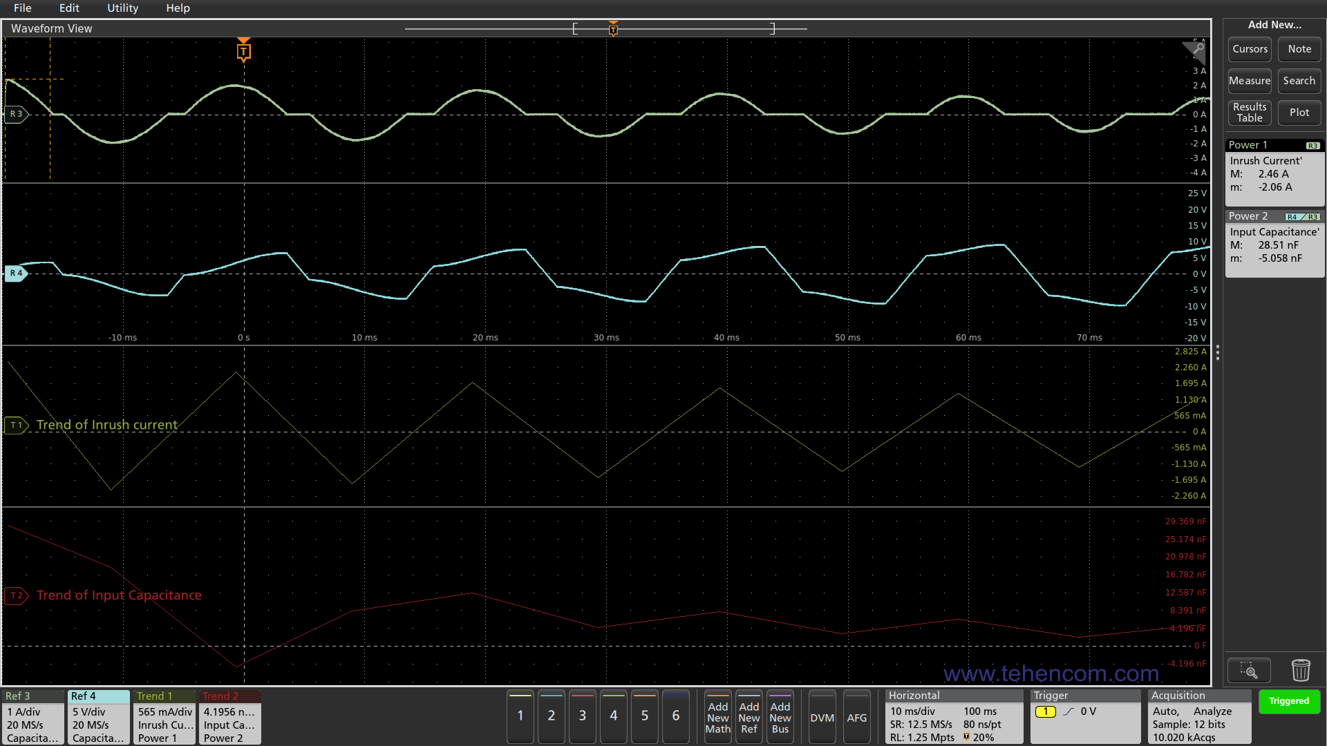
Another group of measurements, which is carried out at the point of connection to the AC mains, includes the measurement of the maximum value starting current (starting current) and related input capacity investigated power source. These parameters must be measured, since the value of the starting current can many times exceed the current consumed by the power source in normal mode.
The MSO4, MSO5, and MSO6 series oscilloscopes can be used for measurement with the appropriate 4-PWR, 5-PWR, and 6-PWR software options. As an example, this screenshot of a Tektronix MSO58 oscilloscope with the 5-PWR option installed shows: on the first graph (upper) the input current signal, on the second graph the input voltage signal, on the third graph the input current boundary at each half-cycle of the input voltage and on the fourth graph of the boundary of the input capacitance change at each half-cycle of the input voltage.
The right side of the screenshot shows the main numerical results of this group of measurements: the maximum starting current of 2.46 A and the maximum input capacitance of 28.51 nF.
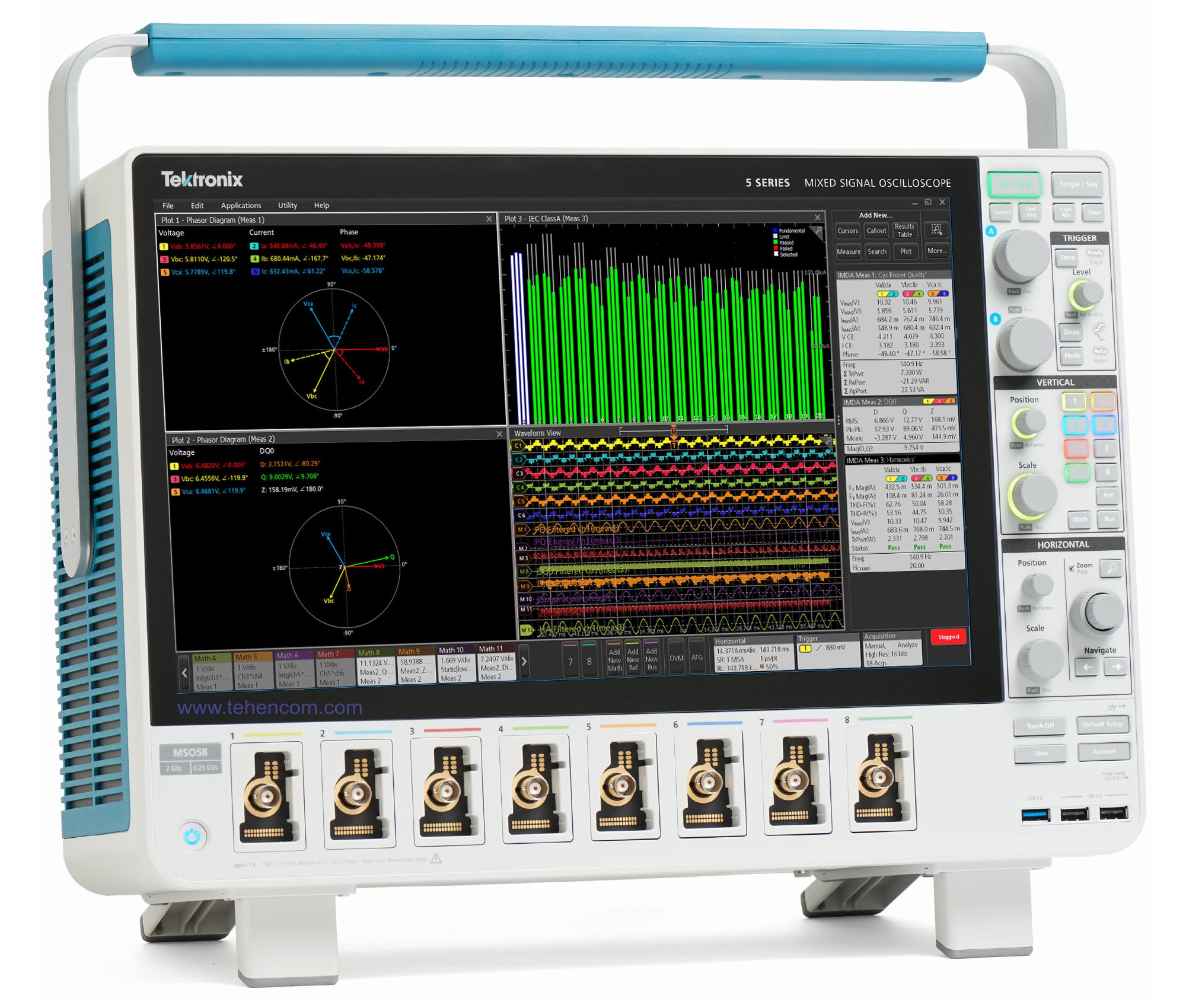
In the study of electricity conversion devices connected to a three-phase network, including inverter motor drives, it is optimal to use the MSO58 eight-channel oscilloscope with the 5-IMDA option or the MSO68B with the 6-IMDA option. These models, equipped with the IMDA option, are capable of performing dozens of types of measurements specific to three-phase systems. The photo below shows the MSO58 oscilloscope with the results of the IMDA option.
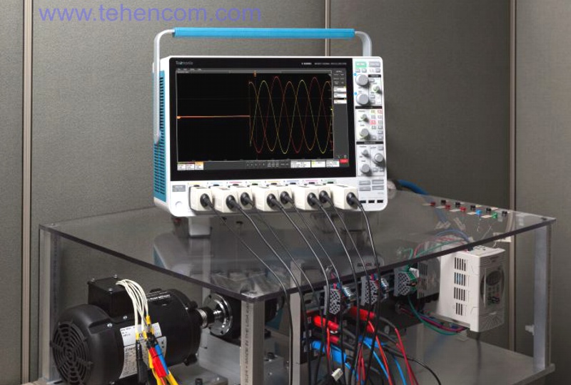
A good example of the oscilloscope's versatility when making measurements at the point of connection to the AC mains is shown in this photo. It shows a Tektronix MSO58 eight-channel oscilloscope with a set of probes, analyzing transients during start-up of a three-phase electric motor.
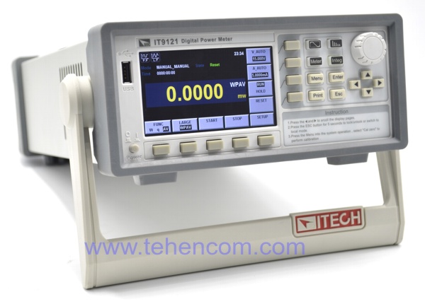
In addition to the oscilloscope, multifunctional electrical power and energy meters, such as ITECH IT9121 shown in this photo.
Using such a device, you can accurately measure: voltage, current, active power, reactive power, apparent power, power factor, phase angle, energy, harmonics (up to 50) and other important parameters. At the same time, the cost of such a device is much lower than the cost of an oscilloscope with a set of necessary probes.
Measurement of the characteristics of the internal components of the power supply
If the power supply being developed is a switching power supply, then it contains one or more continuously switching power transistors. The switching frequency is usually from tens to hundreds of kHz. During the switching process, these transistors dissipate power, which can lead to overheating, and are also subjected to overloads due to transients in reactive elements, which can lead to breakdown.
To improve the overall efficiency and reliability of the power supply, it is necessary to measure the following parameters: switching losses (Switching loss) и safe working area (SOA - Safe Operating Area).
Since the voltage across a transistor in the "off" state can be hundreds or thousands of times greater than the voltage in the "on" state, an oscilloscope with an ADC of 12 bits or more is needed to accurately measure switching losses. A standard oscilloscope with an 8-bit ADC will not be able to measure this ratio correctly in most cases.
A differential probe is almost always used to measure voltage. In some cases, when even a differential probe cannot suppress common mode noise, it is recommended to use an optically isolated probe. TIVM IsoVu.
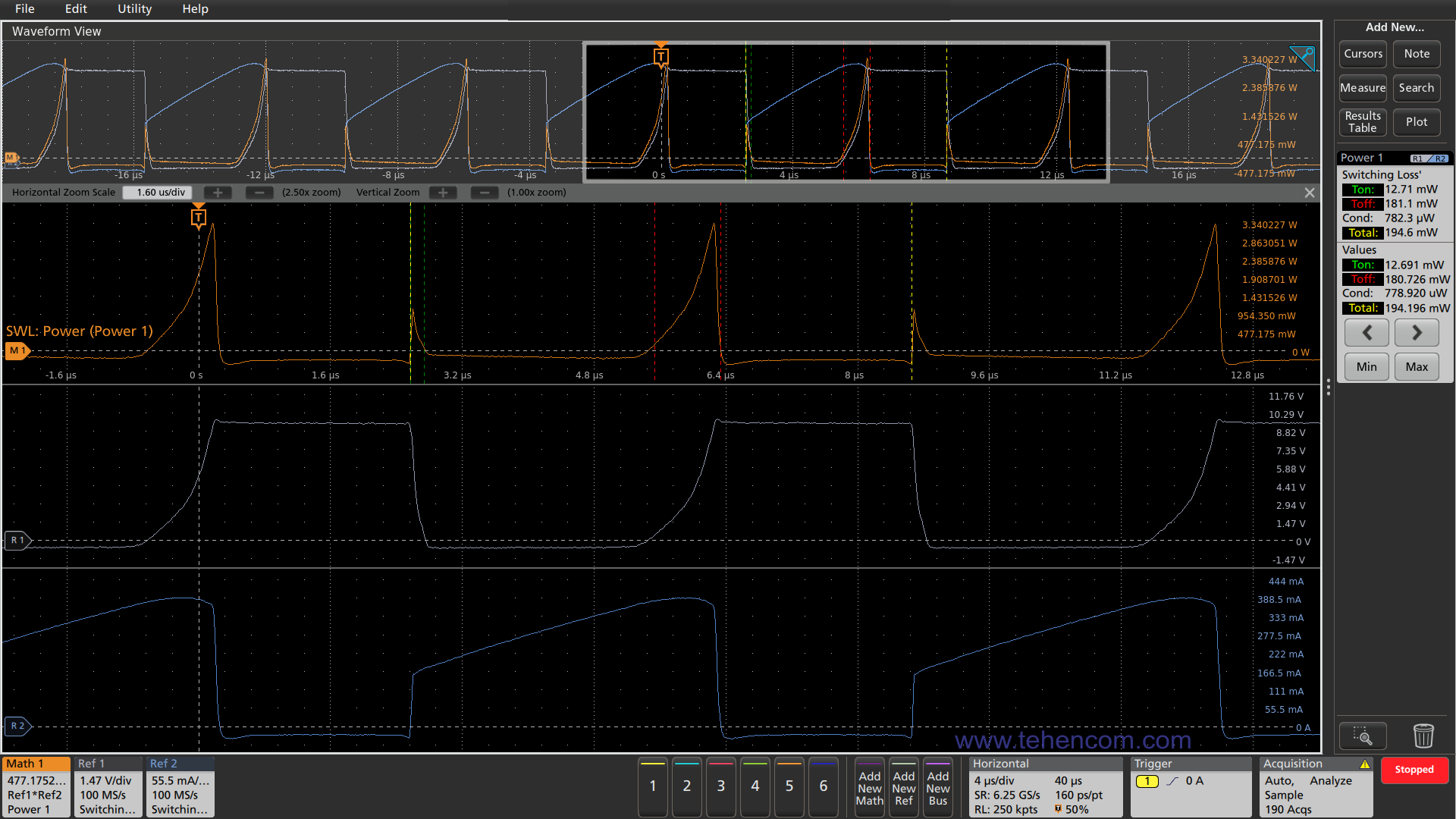
The MSO4, MSO5, and MSO6 series 12-bit ADC oscilloscopes with the appropriate 4-PWR, 5-PWR, and 6-PWR software options are best suited for measuring switching loss. For example, this screenshot of a Tektronix MSO58 oscilloscope with the 5-PWR option installed shows: the current flowing through the transistor (lowest graph), the voltage across the transistor (second graph from the bottom), and the switching loss of the transistor in Watts (third graph from the bottom). The topmost graph is all the transistor on-off cycles measured by the oscilloscope.
The right side of the screenshot shows the main numerical results of this group of measurements: turn-on losses (Ton = 12.71 mW), turn-off losses (Toff = 181.1 mW) and total average losses (Total = 194.6 mW).
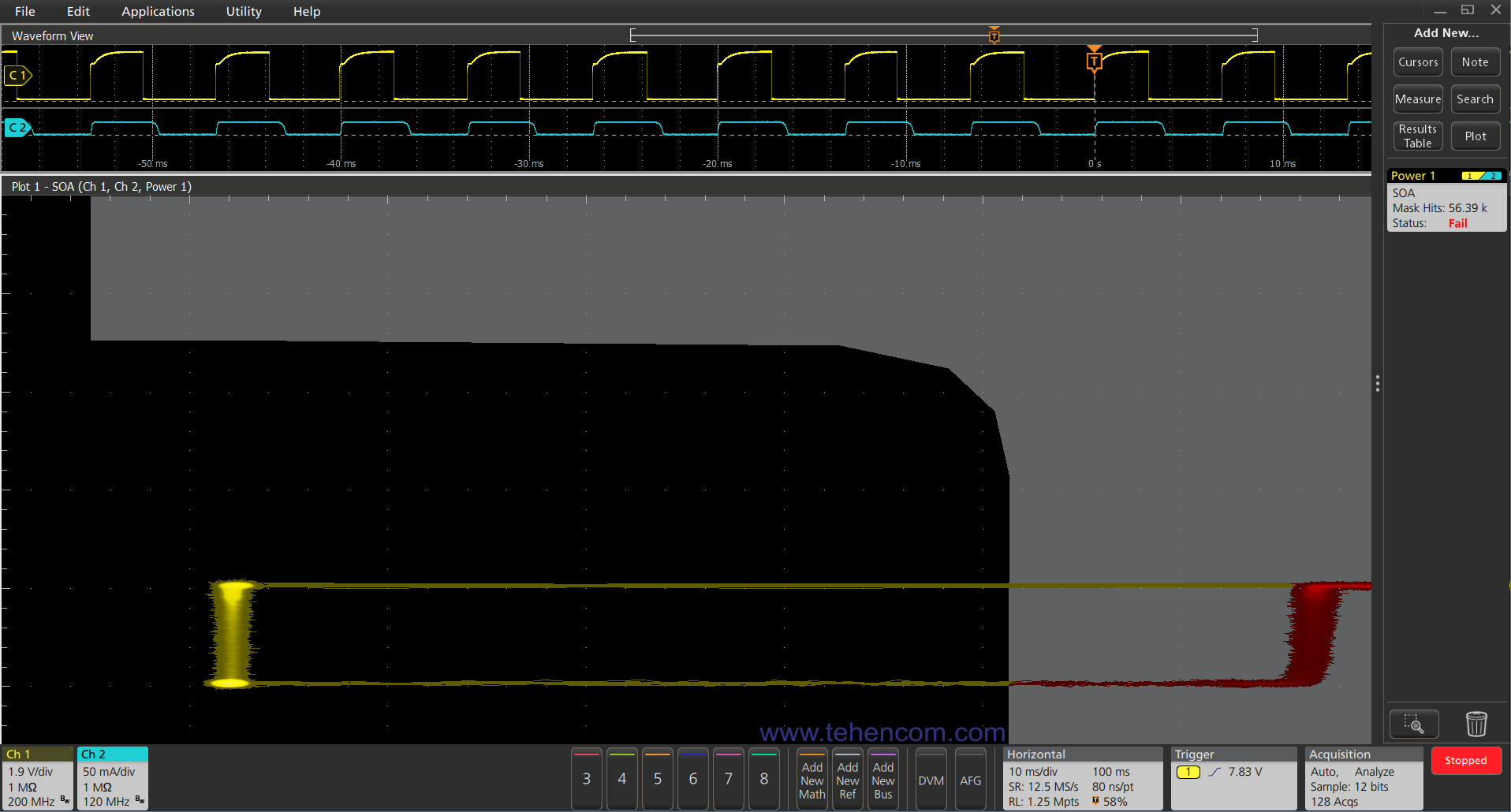
Power transistor manufacturers indicate for these components safe working area (SOA - Safe Operating Area), which determines the maximum safe currents flowing through the transistor, at different values of the voltage applied to it. It is critical that the transistor always operates within its safe region, regardless of variations in input voltage, load power, or temperature.
To measure the area of safe operation, you can use oscilloscopes of the series Tektronix MDO3 with the 3-PWR software option, and MSO4, MSO5, and MSO6 series oscilloscopes with the corresponding 4-PWR, 5-PWR, and 6-PWR software options. Series MSO4 and MSO5 are optimal.
For example, this screenshot of a Tektronix MSO58 oscilloscope with the 5-PWR option installed shows the safe area of the transistor under test (black part on the left), the area of overload and possible failure (gray part on the right and top) and the yellow-red graph reflecting the measured parameters operation of this transistor. It can be seen that the transistor operates with a significant overload, since it is in the forbidden gray region for a significant part of the cycle.
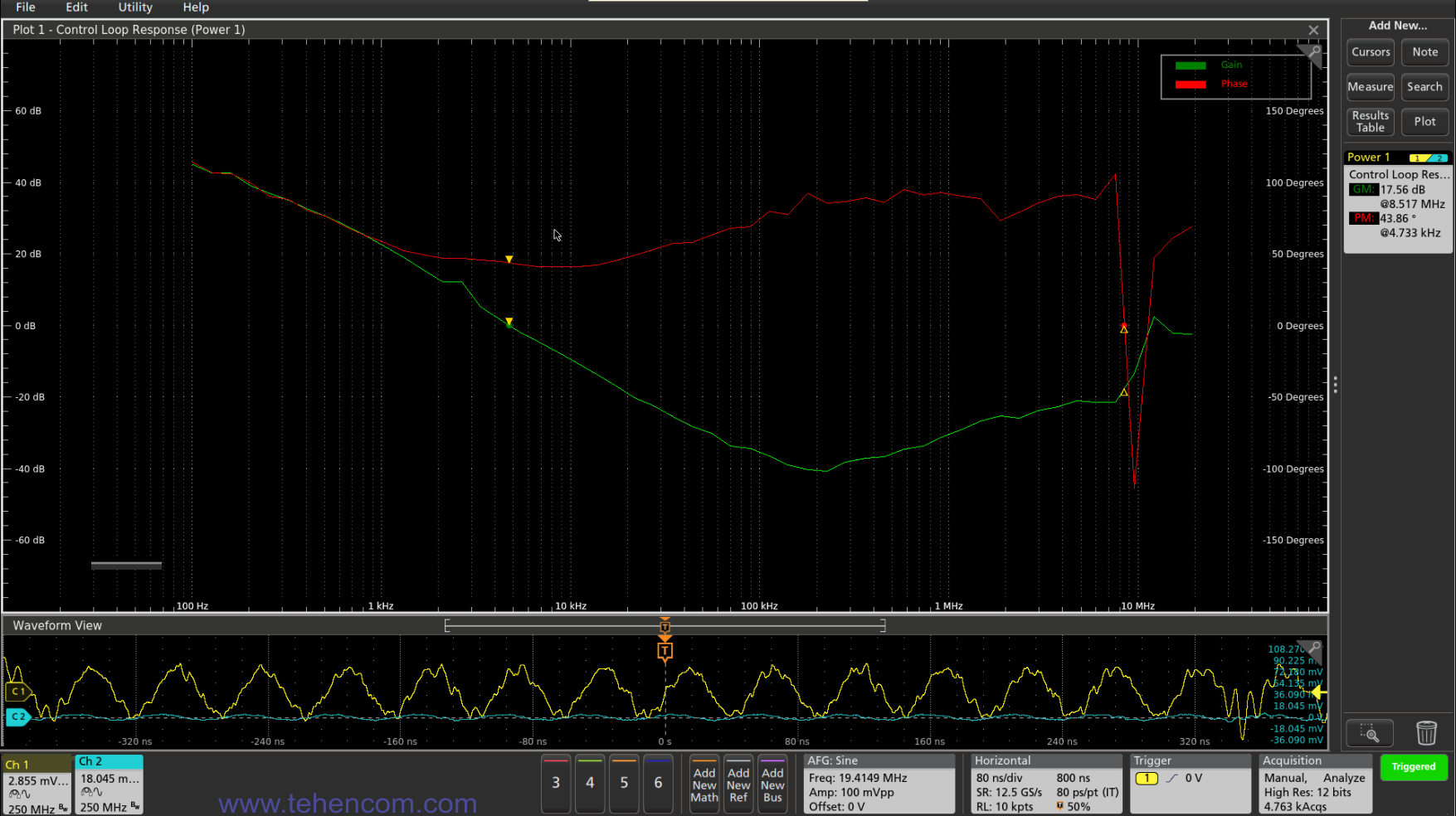
Most power supplies have a feedback circuit built into them to maintain the desired output voltage. Analysis of the stable and efficient operation of this feedback loop is carried out using Bode plots (logarithmic amplitude-phase frequency response). Also, with the help of Bode plots, the operation of the input and output filters is analyzed.
Series oscilloscopes can be used to plot Bode plots. MSO4, MSO5 and MSO6 with the appropriate 4-PWR, 5-PWR and 6-PWR software options, plus an oscillator (built into the oscilloscope or a separate oscilloscope AFG31000). The signal from the generator is fed to the desired point of the power source through an injection transformer of the Picotest J21xxA series. An example of Bode plots plotted with a Tektronix MSO58 oscilloscope with the 5-PWR option is shown in this screenshot.
Almost all switching and linear power supplies contain inductive elements: inductors and transformers. These elements contribute to energy losses and decrease in efficiency, can enter saturation, while significantly changing their characteristics, can be a source of electromagnetic interference, etc. Therefore, measuring the parameters of inductive elements is an important component in the development of an efficient and reliable power supply.
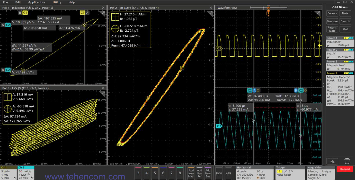
The main parameters that are measured are: inductance, magnetic losses and BH charts. Measurement of magnetic loss can help optimize the overall efficiency of the source, and analysis of the BH graphs allows you to determine the presence or absence of core saturation and a number of other important parameters.
The MSO4, MSO5, and MSO6 series oscilloscopes are best suited for measuring inductive elements with the appropriate 4-PWR, 5-PWR, and 6-PWR software options. If a transformer with three or more windings is being investigated, then for simultaneous measurements it is necessary to use six-channel or eight-channel oscilloscopes (two channels per winding).
For example, this screenshot of a Tektronix MSO58 oscilloscope with the 5-PWR option installed shows the inductance measurement (upper left graph), current versus voltage integral (lower left graph), and the BH graph (center graph). The right side of the screenshot shows voltage (top) and current (bottom) signals.
The rightmost part displays the main numerical results of this group of measurements: inductance (59.84 μH), magnetic losses (91.94 mW) and a number of other parameters.
Measurements at the point of connection to the direct current (DC) network
The measurements described in this section are made at the point where the AC/DC and DC/DC power supplies are connected to the load. The purpose of these measurements is to make sure that the source under study provides the specified values of output voltage, current, ripple and other characteristics with all possible variations in input voltage, load power, temperature and other influencing factors.
In addition, the equipment and techniques presented in this section apply to testing DC/AC and DC/DC power supplies at the point they are connected to the direct current (DC) source that powers them.
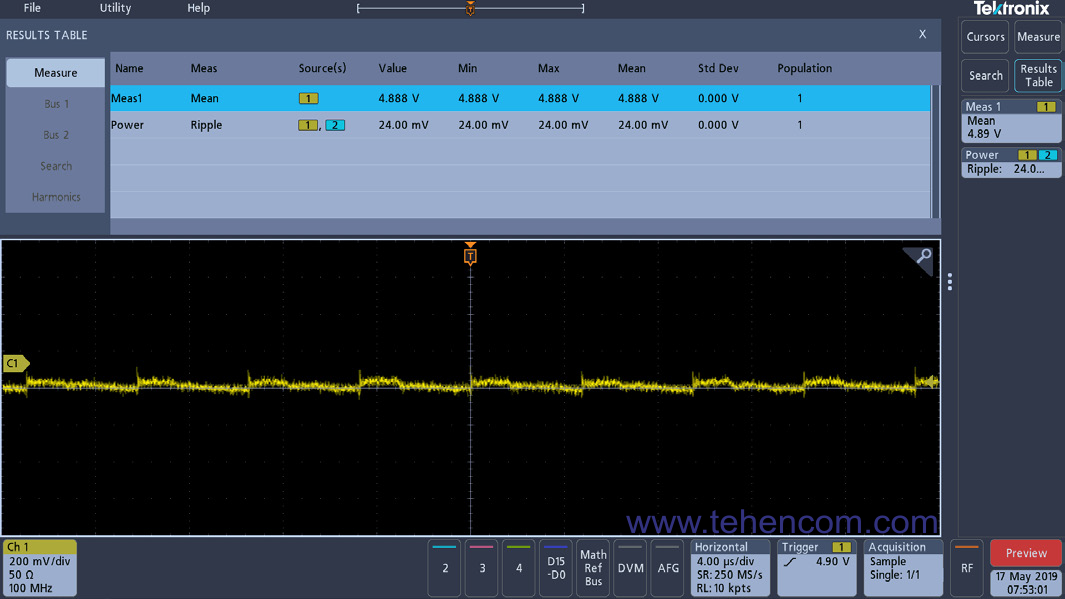
The main measured characteristic is ripple level constant voltage (Ripple). Also for sources of types AC/DC and DC/DC measure DC voltage dependence at their output from the load current.
You can use oscilloscopes for measurement Tektronix MDO3 with software option 3-PWR, as well as oscilloscopes of the series MSO4, MSO5 and MSO6 with corresponding software options 4-PWR, 5-PWR and 6-PWR. To work with multi-channel power supplies, the MSO4 and MSO5 series are optimal, since they have models for 6 and 8 channels with a 12-bit ADC.
For example, this screenshot of a Tektronix MDO34 oscilloscope with the 3-PWR option installed shows a power supply output that contains high-frequency ripple (Ripple) with a repetition period of about 200 kHz. These ripples are caused by switching of the power transistor inside the power supply. At the top of the screen is a table with the results of measurements: DC voltage 4.888 V, ripple 24 mV.
If, in addition to the ripples of the power supply itself, the frequency of which usually does not exceed 1 MHz, it is necessary to measure ripples with frequencies of tens and hundreds of MHz caused by fast switching of the load current (microprocessors, high-speed logic), then it is necessary to use the older series of oscilloscopes (MSO5 or MSO6) and special probes (TPR1000 / TPR4000 1 GHz / 4 GHz). For advanced ripple analysis, such as its effect on digital clock jitter, software tools are recommended. 5-DPM options or 6-DPM.
Measurements between the input and output of the power supply
This is the final group of measurements, which determine the relationship between the signals at the input of the power source and the signals at its output. The main measurements of this group are: efficiency (Efficiency or Efficiency), turn-on time and turn-off time.
The average efficiency can be measured in various ways, for example, using the data of the built-in multimeters of a laboratory power supply at the input of the power source under study and the electronic load at its output. But the universal solution, with which it is possible to measure the dynamic changes in efficiency and the contribution to the efficiency of individual channels of multichannel sources, is based on an oscilloscope.
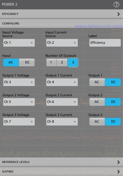
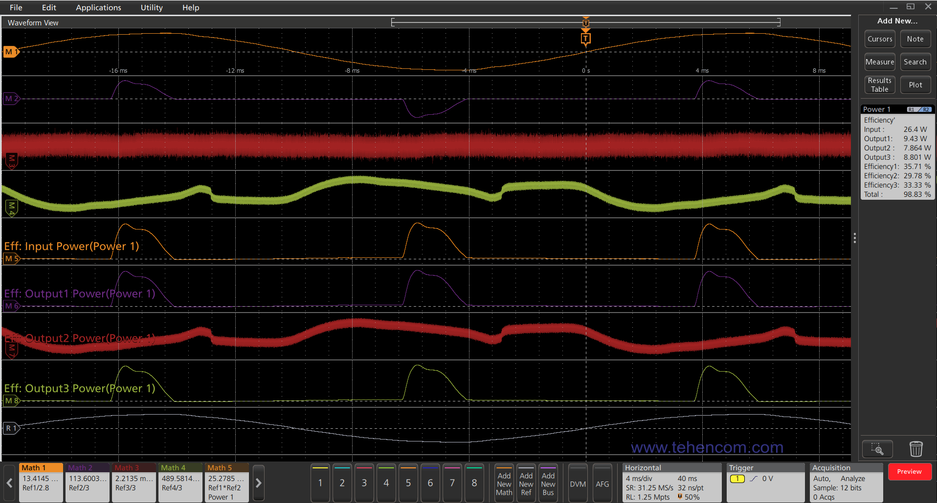
To measure the efficiency, you can use oscilloscopes of the series MSO4, MSO5 and MSO6 with corresponding software options 4-PWR, 5-PWR and 6-PWR. A screenshot of the configuration window of the Tektronix MSO58 oscilloscope before starting efficiency measurements is shown in this figure. Note that you can freely select the type of input (AC or DC), the number of outputs and the type of each output (AC or DC).
This Tektronix MSO58 oscilloscope screenshot shows power graphs at the input of the power supply under test and at each of its three outputs. On the right side of the screen, the overall results are displayed numerically: Efficiency is 98.83%.
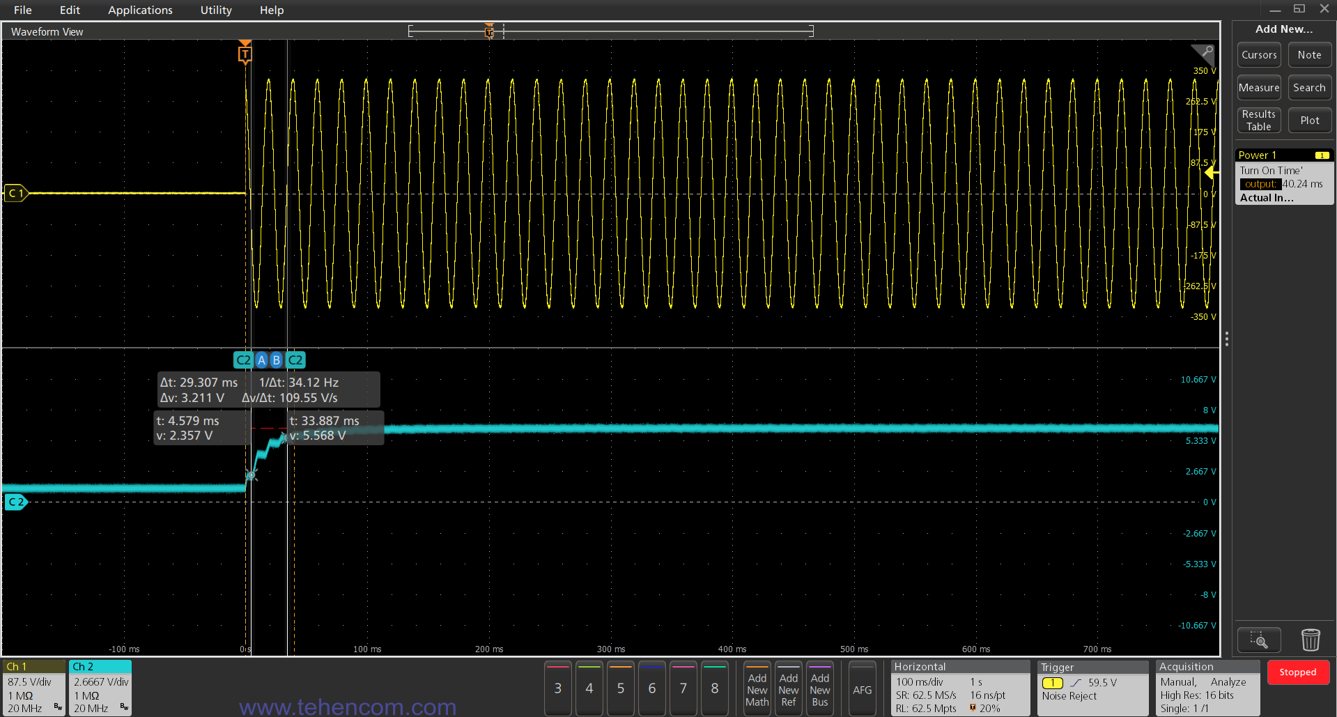
For most types of power supplies, on-time and off-time are important characteristics. In addition, for sources with multiple outputs, it is necessary to measure the synchronism of voltage settling and the resulting delays.
You can use the MSO4, MSO5, and MSO6 series oscilloscopes with the appropriate 4-PWR, 5-PWR, and 6-PWR software options to automatically measure turn-on and turn-off times. With an 8-channel oscilloscope model, you can even examine a single-input power supply and seven exits. An example measurement is shown in this screenshot of a Tektronix MSO58 oscilloscope.
Checking the electrical safety of the power supply
At the final stage of power supply development, a set of electrical safety tests is carried out. Depending on the purpose and design of the developed device, the following can be carried out: testing the dielectric strength of the insulation, measuring the insulation resistance, measuring the resistance of low-resistance circuits, measuring the leakage current, checking the built-in surge protection device, and others.
To carry out these tests, a set of appropriate equipment is required: a punching device, a gigaohmmeter, a milliohmmeter, a high-voltage pulse generator, etc. This equipment is available in the form of separate devices or in the form of multifunctional measuring installations.
As individual appliances can be used: breakdown unit up to 5 kV Sourcetronic ST9201, insulation resistance meter up to 10 TΩ Sourcetronic ST2683A, milliohmmeter from 1 µOhm Sourcetronic ST2516 and high-voltage pulse generator up to 10 kV Sourcetronic ST2883-10.
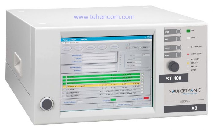
As multifunctional installation modular measuring system recommended Sourcetronic ST400, which can include up to eight different modules that can provide the entire set of electrical safety tests. The appearance of the ST400 system is shown in this photo.
Additional information on this topic
We have deliberately not overloaded this article with the technical details of testing individual power supply components. For a more complete study of existing measurement methods and instruments used in this area, we recommend that you familiarize yourself with this information:
Tektronix 3-PWR Measurement Automation Option Description (6 pages; 1 MB)
Tektronix 4-PWR, 5-PWR, and 6-PWR Measurement Automation Options Description (24 pages; 5 MB)
Tektronix 5-IMDA Measurement Automation Option Description (17 pages; 4 MB)
Switch Mode Power Supply Testing Guide (English) (14 pages; 4 MB)
Automotive Electrical Testing Guide (English) (20 pages; 7 MB)
Oscilloscope Basics Tutorial (in Russian) (60 pages; 2 MB)
How to choose a digital oscilloscope - a detailed guide
How to choose a laboratory power supply - a detailed guide
What is an electronic load - general information
If you need technical advice on the selection of the optimal set of equipment for the development and production of your power supply or power converter, just call us or write to us at E-mail and we will be happy to answer your questions.