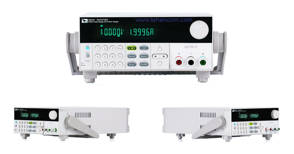
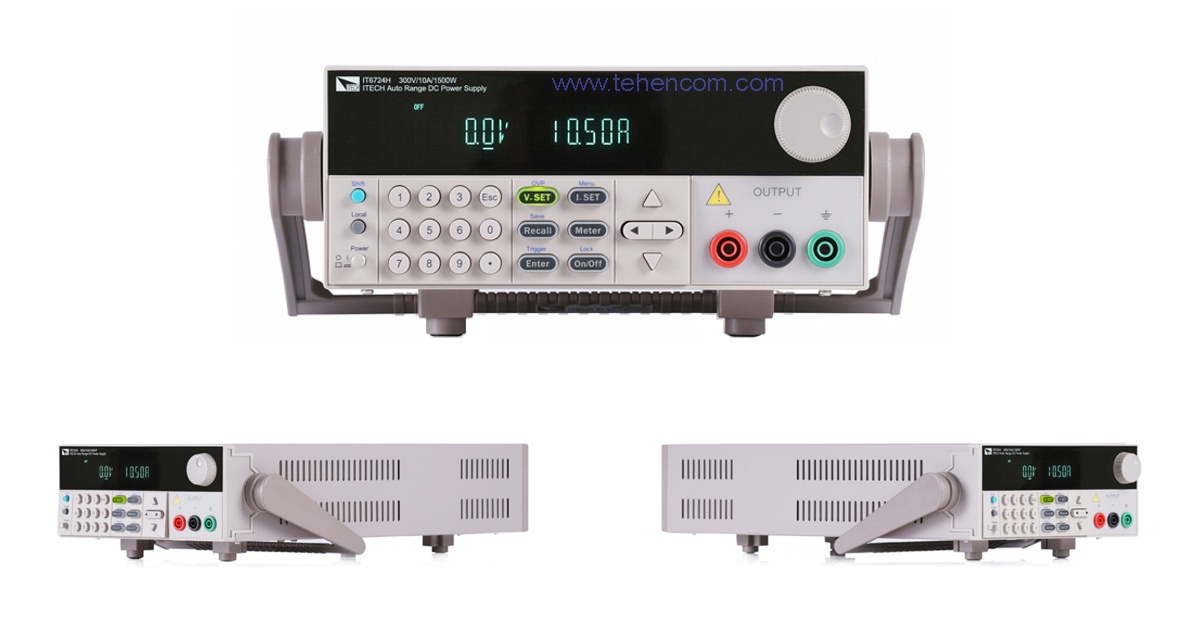
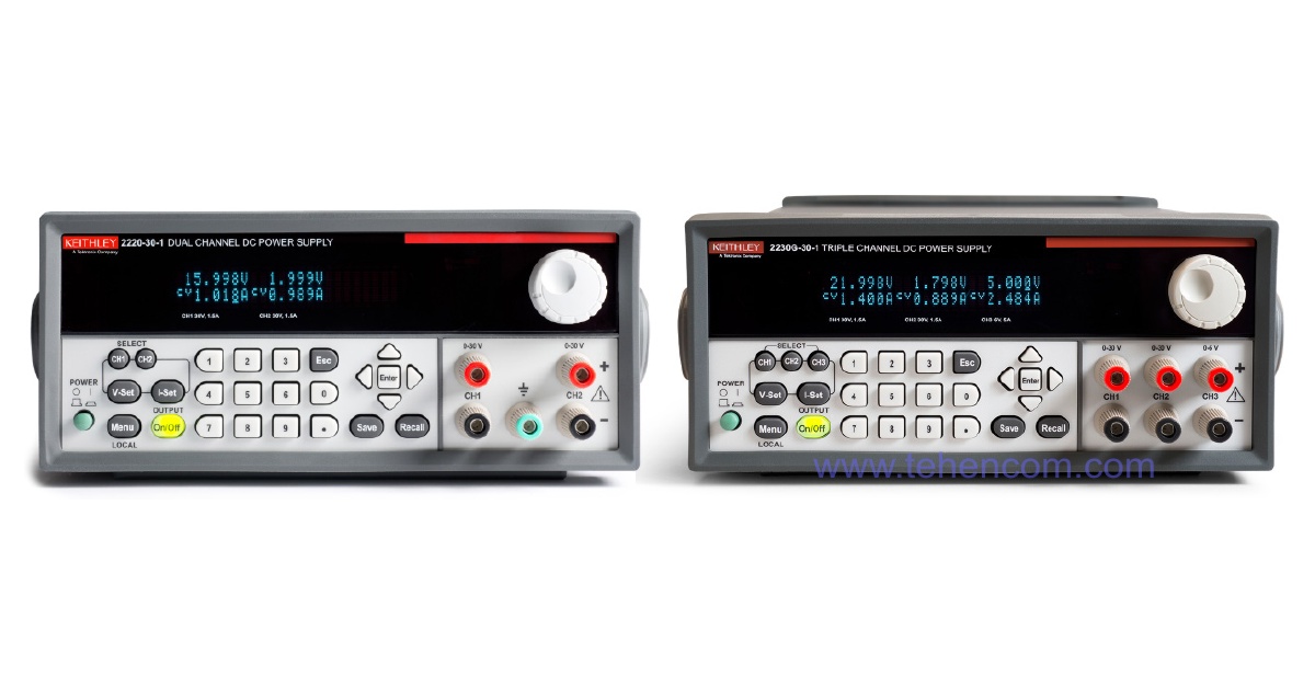
Choosing a laboratory power supply
Brief introduction
The laboratory power supply (LPS) market offers many series from various manufacturers. Some models attract with a low price, others with an impressive front panel, others with a variety of functions. Therefore, the correct choice of such a common device becomes a difficult task. At the same time, a thorough comparison of the characteristics and capabilities of models from different manufacturers may not answer the main question: Which lab power supply is best for my needs?
Most engineers consider a laboratory power supply to be a very simple device whose only function is to supply the load with a given voltage and current. But in practice, things are not so simple. Voltage drop in the connection wires, impulse noise, voltage surges with a rapid change in the current consumption of the load – these are just some of the aspects that must be taken into account. In some cases, it may be necessary to galvanically isolate the outputs of a laboratory power supply, and in some tasks it is necessary that the LPS add predetermined distortions (jumps, drops) to its output voltage in order to check how the device will behave with an unstable power supply.
In this article, relying on our experience, we will talk about simple criteria for choosing the optimal laboratory power supply, their varieties, differences and advantages. Next, we will consider several typical tasks and offer models of power supplies for each of them, choosing which you can work efficiently and save your money, time and nerves. After that, it will be much easier for you to choose and buy laboratory power supply in the relevant section of our website.
Varieties of laboratory power supplies
First, let's deal with the existing titles. What is the difference between a laboratory power supply and a simple power supply? Or what is the difference between a power supply and a power supply? Here are the simple definitions:
1. Laboratory power supply called a device that is designed to generate an adjustable voltage or current through one or more channels. The laboratory power supply contains a display, controls, protection against misuse, and useful additional features. All the material on this page is dedicated to such devices.
2. Laboratory Power Supply – this is the same as the laboratory power supply.
3. Simple power supply called an electronic device that is designed to generate a predetermined voltage through one or more channels. The power supply, as a rule, does not have a display and control buttons. A typical example is a several hundred watt computer power supply.
4. Power supplies There are two types: primary power supplies and secondary power supplies. Primary power sources convert non-electrical forms of energy into electrical energy. Examples of primary sources: electric battery, solar battery, wind generator and others. Secondary power supplies convert one type of electrical energy into another to provide the necessary voltage, current, frequency, ripple, etc. parameters. Examples of secondary power supplies: transformer, AC/DC converter (such as computer power supply), DC/DC converter, voltage regulator, etc. By the way, the laboratory power supply is one of the varieties of the secondary power supply.
Now let's discuss in detail the varieties and main characteristics of laboratory power supplies:
1. According to the principle of work: linear or pulse.
2. Voltage and current range: fixed or with automatic power limitation.
3. Number of channels: single-channel or multi-channel.
4. Channel isolation: with galvanically isolated channels or non-isolated.
5. By power: standard or high power.
6. Presence of protection: from overvoltage, overcurrent, overheating and others.
7. Output waveform: constant voltage and current or alternating voltage and current.
8. Control options: manual control only or manual plus software control.
9. Price level: from cheap to expensive.
10. Additional functions: compensation for voltage drop in the connection wires, built-in precision multimeter, changing the output according to the list of set values, activating the output by timer, simulating a battery with a given internal resistance, built-in electronic load and others.
11. Reliability: the quality of the element base, thoughtfulness of design, thoroughness of the output control.
Let's consider each of these characteristics in more detail, since they are all important for the correct and informed choice of a laboratory power supply.
Operating principle: linear and switching
Linear power supply (it is also called a transformer power supply) is built on the basis of a large low-frequency transformer, which lowers the input voltage of 220 V, 50 Hz to several tens of volts with a frequency of also 50 Hz. After that, the reduced sinusoidal voltage is rectified using a diode bridge, smoothed by a group of capacitors, and lowered by a linear transistor regulator to a predetermined level. The advantage of this principle of operation is the absence of high-frequency switching elements. The output voltage of the linear power supply is accurate, stable and does not contain high frequency ripple. This photo shows the internal construction of a linear laboratory power supply. ITECH IT6833, on which the numbers indicate: the main transformer (1) and smoothing capacitors (2).
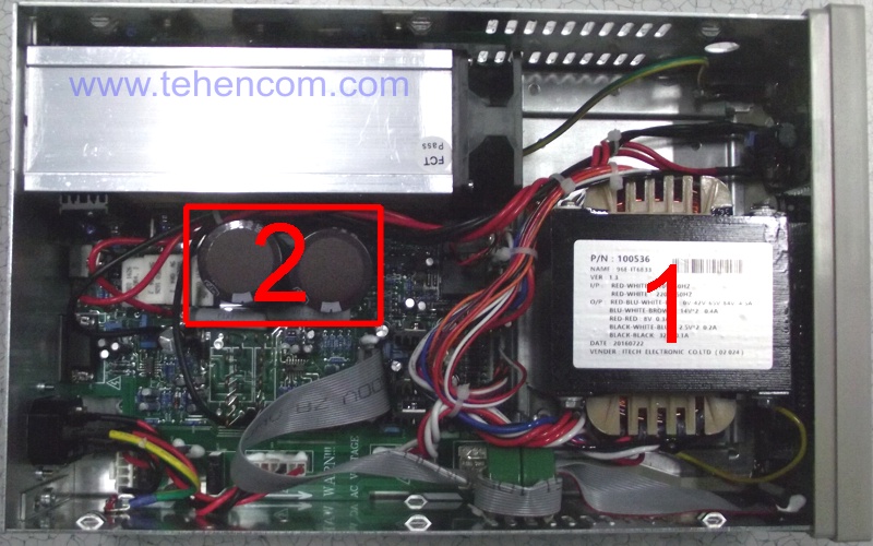
However, the linear power supply has many disadvantages. The main one is the large energy losses on the transistor stabilizer, which converts into heat all the excess voltage supplied to it from the rectification circuit. For example, if the output voltage of the power supply is set to 5 V, and the rectified voltage of the secondary winding is 25 V, then 4 times more power will be dissipated in the transistor regulator than will be supplied to the load. That is, a linear power supply has a low coefficient of performance (COP), usually less than 60%. As a result of low efficiency, we get a small useful power and increased mass. To improve the situation, in real devices several secondary windings of the transformer are used, but this still does not completely solve the problem of low efficiency.
Therefore, commercially available linear laboratory power supplies provide power at a load of up to 200 W with a device weight of 5 to 10 kg. There are two more problems that are rarely talked about. Although the linear power supply itself does not create high-frequency interference, it can still easily penetrate from the 220 V supply network through the capacitive coupling of the primary and secondary windings of the main transformer. In expensive models, constructive solutions are used to combat this effect, for example, ferrite filters, but interference from the power supply can still appear at the output of the device, and this feature must be remembered. If you need the purest possible DC voltage, then it makes sense to use an additional high-quality line filter in front of the laboratory power supply. The second problem is the degradation (drying out) of the smoothing capacitor group, especially in cheap models. With a significant decrease in the capacitance of a group of smoothing capacitors, voltage dips with a frequency of 100 Hz will appear at the output of the power supply.
Impulse power block is based on the principle of charging smoothing capacitors with current pulses. Current pulses are generated by connecting and disconnecting an inductive element, which can be a transformer winding or a separate inductive component. Switching is done by transistors specially optimized for this purpose. The frequency of current pulses thus formed is usually in the range from tens of kHz to hundreds of kHz. Adjusting the output voltage is most often done by changing the depth of pulse-width modulation (PWM).
There are many ways to implement this principle, but they all provide two main advantages. The first is high efficiency, usually over 80%, sometimes over 90%. High efficiency is achieved due to the fact that the PWM depth can be very smoothly changed, which means that exactly as much energy can be pumped into smoothing capacitors as the load of the power supply consumes. The second advantage is small size and low weight. The high frequency at which the switching power supply operates allows the use of much smaller capacitors (when compared with a 50 Hz linear power supply). The remaining elements are also much more compact and lighter, and high efficiency reduces the heat generated inside the power supply, which also reduces the size of the structure.
This photo shows the internal construction of a switching laboratory power supply. ITECH IT6942A, on which the numbers indicate: the main transformer (1) and the pulse converter (2). Please note that the body of this device is exactly the same size as the linear model in the previous photo, and the power is 1.7 times higher.
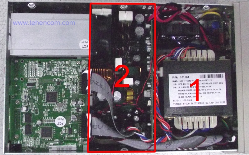
The main disadvantage of switching power supplies is the high-frequency ripple of the output voltage. Of course, they are smoothed, filtered, but some level of ripples still remains. Moreover, the more the power supply is loaded, the greater the amplitude of the ripples. In good, high-quality switching power supplies, it is possible to reduce ripple to a level of 10 - 20 mV. The second, not so obvious, disadvantage is radio frequency pickups and their harmonics, the source of which are periodic current pulses generated inside the power supply. Such pickups are quite difficult to shield. If you are working with RF circuits, then use a linear power supply or a quality switching power supply, located away from the radio device you are working with.
Voltage and current range
Modern laboratory power supplies have two types of output voltage and current ranges: fixed and with automatic output power limitation.
Fixed range is found on most inexpensive laboratory power supplies. Such power supplies can deliver any combination of voltage and current within their maximum ratings. For example, a single-channel laboratory power supply for 40 V and 15 A can maintain a voltage of 40 volts at a load even at a current consumption of 15 amperes. In this case, the power consumed by the load will be: 40 V * 15 A = 600 W. Everything is simple and clear, but with such a device you will not be able to set a voltage of more than 40 V and a current of more than 15 A.
Automatic output power limitation significantly expands the range of the laboratory power supply in terms of voltage and current. For example, model ITECH IT6952A with the same maximum power of 600 W, it can generate voltage up to 60 V and current up to 25 A in any combination, in which the output power is limited to 600 W. This means that you can supply not only 40 V at 15 A, but also 60 V at 10 A, 24 V at 25 A and many other combinations. Compared to a fixed range 600W lab power supply, it is clear that the auto-limiting lab power supply is much more versatile and can replace several simpler devices. This figure shows the range of possible voltages and currents provided by the ITECH IT6952A.
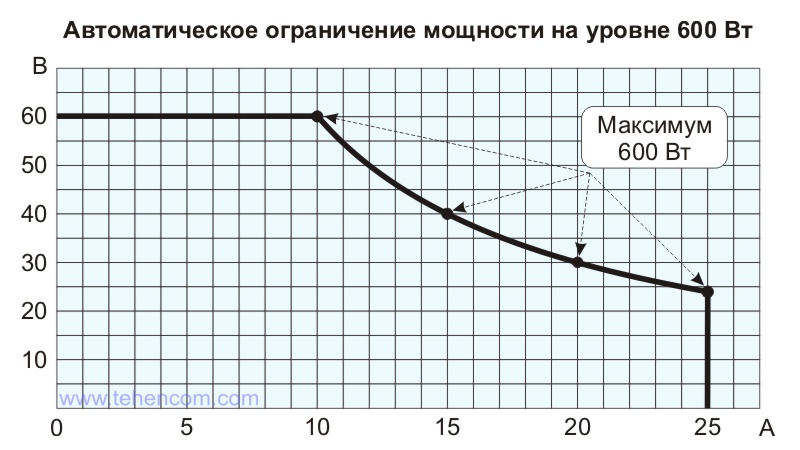
Since the dimensions, weight and price of a laboratory power supply do not mainly depend on voltage and current, but on maximum power, it makes sense to always choose a model with automatic output power limiting. This will provide a universal solution for the same money.
Number of channels
Laboratory power supplies are available with one, two or three output channels. Here we will consider the main points of their use, and the galvanic isolation of channels is described further on this page.
Most laboratory power supplies have one output channel, especially for powerful devices. Almost all models with a power of more than 500 W have one channel. Therefore, the question is often asked: is it possible to combine several single-channel devices? It is possible, but there are some peculiarities. The first thing to consider when you turn on several switching power supplies in series: the switching frequencies of even the same type of power supplies will differ slightly. This will create increased ripple at the output. There is also the possibility of resonant effects, in which the level of pulsations will periodically increase sharply.
The second point is the connection "+" and "-" of two devices for the formation of a bipolar voltage for powering transistor amplifiers, ADCs and similar devices. In addition to increased ripples, it will be difficult to ensure the simultaneous switching on and off of two voltages at once and their synchronous adjustment. The third point – the series connection of several high-voltage voltage sources can exceed the breakdown threshold of their insulation. As a result: fire and other dangerous consequences.
Given the above, it becomes clear that for circuits in which several supply voltages are provided, it is better to use two-channel or three-channel laboratory power supplies, which are specially designed for this. And to generate high voltages, it is better to use special high-voltage models, for example, the model ITECH IT6726V with voltage up to 1200 V or model ITECH IT6018C-2250-20 with voltage up to 2 250 V.
For example, this photo shows a typical two-channel laboratory power supply. ITECH IT6412.
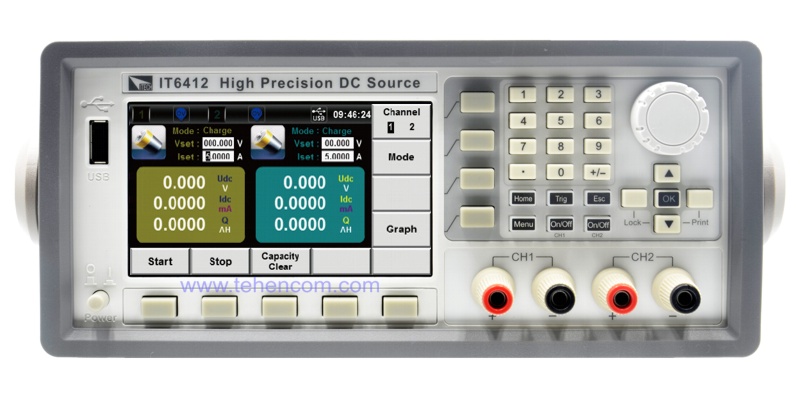
Channel isolation
Galvanic isolation (also called electrical isolation) of the laboratory power supply channels ensures complete independence of the voltage and current of any of the channels relative to the voltage and current of the remaining channels, as well as the power supply network. Inside such a power supply, for each of the channels, a separate transformer winding is provided. In good models, the breakdown voltage between channels exceeds 200 volts. In practice, this means that you can freely connect channels to each other in series, as well as change "+" and "-".
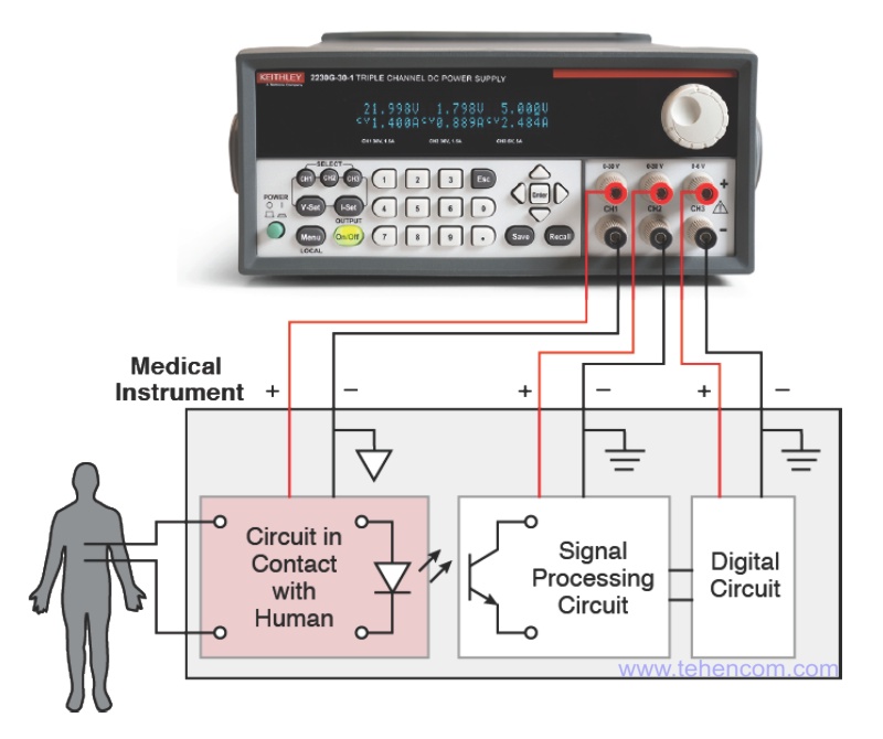
Electronic devices containing digital and analog parts usually use two separate power circuits. This is done in order to reduce the penetration of noise from the digital power rail into the sensitive analog part. Therefore, when developing and configuring such devices, it is necessary to use a laboratory power supply with galvanically isolated channels. The most versatile solution are three-channel models, for example Keithley 2230 or ITECH IT6300B. Using such a device, you can power the analog part of the circuit with a bipolar power supply (the first two channels are used), and power the digital part from the third channel.
Another type of device that requires a laboratory power supply with isolated channels is devices that themselves contain isolated parts. The isolation of parts of such devices is usually carried out using optocouplers or special transformers. A classic example is an electrocardiograph, in which the sensitive measuring analog part connected to the patient must perform two tasks: accurate measurement of the electrical potentials generated by the heart muscle (and this is a level of several millivolts) and the safety of the patient himself from electric shock.
This photo shows the connection diagram of the model Keithley 2230G-30-1 to the main nodes of the cardiograph. The first channel is used to power the very sensitive meter behind the optocoupler, the second channel is used to power the primary signal processing unit, and the third low voltage, high current channel powers the main digital signal processing and display circuitry. Due to the fact that all three channels of the Keithley 2230G-30-1 model are completely isolated from each other, the cardiograph powered in this way works normally and the influence of some blocks on others due to interference passing through the power circuits is excluded.
Power
According to the useful power delivered to the load, all laboratory DC power supplies can be divided into standard (up to 1 000 W) and high power (1 000 W or more). This division is not accidental. Models of standard and high power are quite different in terms of functionality and scope.
On standard power models the maximum voltage is usually in the range from 15 V to 150 V, and the maximum current is from 1 A to 25 A. Number of channels: one, two or three. There are both linear and impulse models. Design: standard instrument case for placement on a laboratory bench. Weight from 2 to 15 kg. Typical example: series Tektronix PWS4000. Basically, the capabilities of such devices are aimed at the development and repair of electronic equipment, although their scope is much wider.
On the other hand, high power models always single-channel and pulsed. Models up to 3 kW are available in instrument or rack versions (typical example: series ITECH IT6700H), and models with a power of 3 kW and more powerful are mounted only in an industrial rack and differ in significant weight and dimensions. For example, the weight of the 18 kW model from the series ITECH IT6000C is 40 kg.
High power puts forward increased requirements for the design: the presence of "smart" cooling fans, a full set of protections (against overload, overheating, polarity reversal, etc.), the possibility of parallel connection of several units to increase output power, support for special forms of output signals (for example, automotive standards DIN40839 and ISO-16750-2).
For this category of devices, it is mandatory to support remote program control via one of the interfaces: Ethernet, IEEE-488.2 (GPIB), USB, RS-232, RS-485 or CAN, as they are often used as part of automated systems. Also, some series (eg. IT6000C) can adjust their output impedance from zero to a few ohms, which is very useful when simulating the operation of batteries and solar panels. In addition, some powerful models may contain a built-in electronic load, which allows them not only to generate current, but also to consume it.
High power laboratory power supplies are used in the automotive industry, alternative energy, metal plating and many other industries where it is necessary to generate voltages up to 2 250 Volts and currents up to 2 040 Amps.
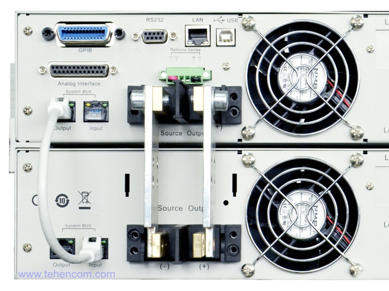
For specifications of all laboratory power supplies, sorted by increasing maximum power, see here. And in this photo you can see the powerful output terminals of the six-kilowatt model IT6533D, which consists of two modules of 3 kW each connected in parallel. Uniform distribution of output power between the modules is ensured using a separate System BUS (gray cable on the left).
Protection against misuse
When choosing a laboratory power supply, first of all, pay attention to the price and the maximum value of voltage and current. But the presence of high-quality protection is also very important, as it allows you to protect not only the power supply, but also the equipment connected to it. In this section, we will talk about the types of protection that commercial laboratory power supplies are equipped with and consider several related points.
Over current protection (abbreviated as OCP - Over Current Protection) should instantly work when the output current exceeds the set value, which can happen, for example, when the output terminals of the power supply are short-circuited. This type of protection is in most good models. But not only the presence of protection is important, the speed of its operation is also important. Depending on the implementation, overcurrent protection can: completely turn off the power supply output from the load, limit the output current to a specified threshold level, or switch to the output current stabilization mode (CC - Constant Current), maintaining the current value that was before the overload. This short video shows how the protection of a low-power laboratory power supply works. ITECH IT6720 short circuit of its outputs.
Voltage overload protection (abbreviated as OVP - Over Voltage Protection) is triggered when the voltage level at the output terminals of the power supply unit exceeds the specified value. This situation can occur when operating on a load with increased resistance in the current stabilization mode. Or when external voltage is applied to the terminals of the laboratory power supply. Another application of this type of protection is to limit the output voltage of the power supply to a level that is safe for the connected equipment. For example, when powering a digital circuit with a voltage of 5 Volts, it makes sense to set 5.5 Volts as the protection threshold in the power supply settings.
Power overload protection (abbreviated OPP - Over Power Protection) is available in all models with automatic output power limitation. The purpose of this protection is to limit the maximum power that the laboratory power supply delivers to the load, so that the power components of the power supply work in normal mode and do not overheat. If, when operating in the output voltage stabilization mode (CV - Constant Voltage), the current consumption is exceeded, the device will automatically switch to the output current stabilization mode (CC - Constant Current) and begin to reduce the voltage at the load.
Overheat protection (abbreviated as OTP - Over Temperature Protection) is triggered by increased heating of the power components of the power supply located inside the case. In simple models, one temperature sensor is used, which is simply soldered into the control board. It monitors the average temperature inside the case and is not able to quickly respond to dangerous heating of power elements. In good models, several sensors are used, located right at the points of maximum heat generation. This implementation provides guaranteed protection of the device, even with rapid local overheating. Usually in good models, overheating protection works in conjunction with cooling fans with variable speed. The more heat generated inside the appliance, the higher the fan speed. If the internal temperature still approaches the critical temperature,
Also in laboratory power supplies there are such types of protection: from polarity reversal (reverse), from low voltage (UVP - Under Voltage Protection) and from emergency shutdown.
Output waveform
The main function of a laboratory power supply in voltage stabilization (CV) mode is the formation of a given constant voltage and its precise maintenance, even with a changing load current. Similarly, in current constant mode (CC), the power supply must supply the specified constant current to the load and ensure that it is accurately maintained even with changing load resistance.
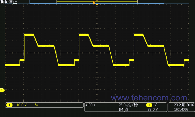
But in modern laboratory and production conditions, it often becomes necessary to change the output voltage according to a certain law. Therefore, some models of good laboratory power supplies provide such an opportunity. This mode is called: "The mode of changing the output voltage according to the list of set values". With it, you can change the output voltage according to a given program, which consists of a sequence of steps. For each step, the voltage level and its duration are set. This mode allows you to test equipment by applying non-ideal signals to it, as close as possible to those that exist in reality: power surges and ripples, short-term power outages, smooth rise and fall, etc.
This photo shows one of the voltage waveforms that can easily be implemented using the List Mode Output Voltage (also called List Mode). The photo was taken using an oscilloscope connected to the power supply terminals IT6500.
But not all tasks can be solved using a laboratory direct current (DC) power supply, even if it has a list mode of operation. There are tasks where it is necessary to form a purely sinusoidal voltage, moreover, with a level of hundreds of volts or a sinusoidal current with a level of tens of amperes. For such tasks, specialized sources of alternating voltage and current are produced, such as a single-phase series ITECH IT7300 or three-phase series ITECH IT7600.
With the help of such devices, many interesting solutions can be implemented, mainly in the field of checking the stability of equipment with various deviations in the 220 V power supply. This short video, using the IT7322 model as an example, shows the formation of an alternating voltage, the amplitude and frequency of which changes according to a given program. The shape of the output signal is observed using an oscilloscope.
Control options: manual and software
Only manual control is typical for budget series, which are very price-critical, for example, for economy series ITECH IT6700. But most good mid to high price lab power supplies support both manual and software control.
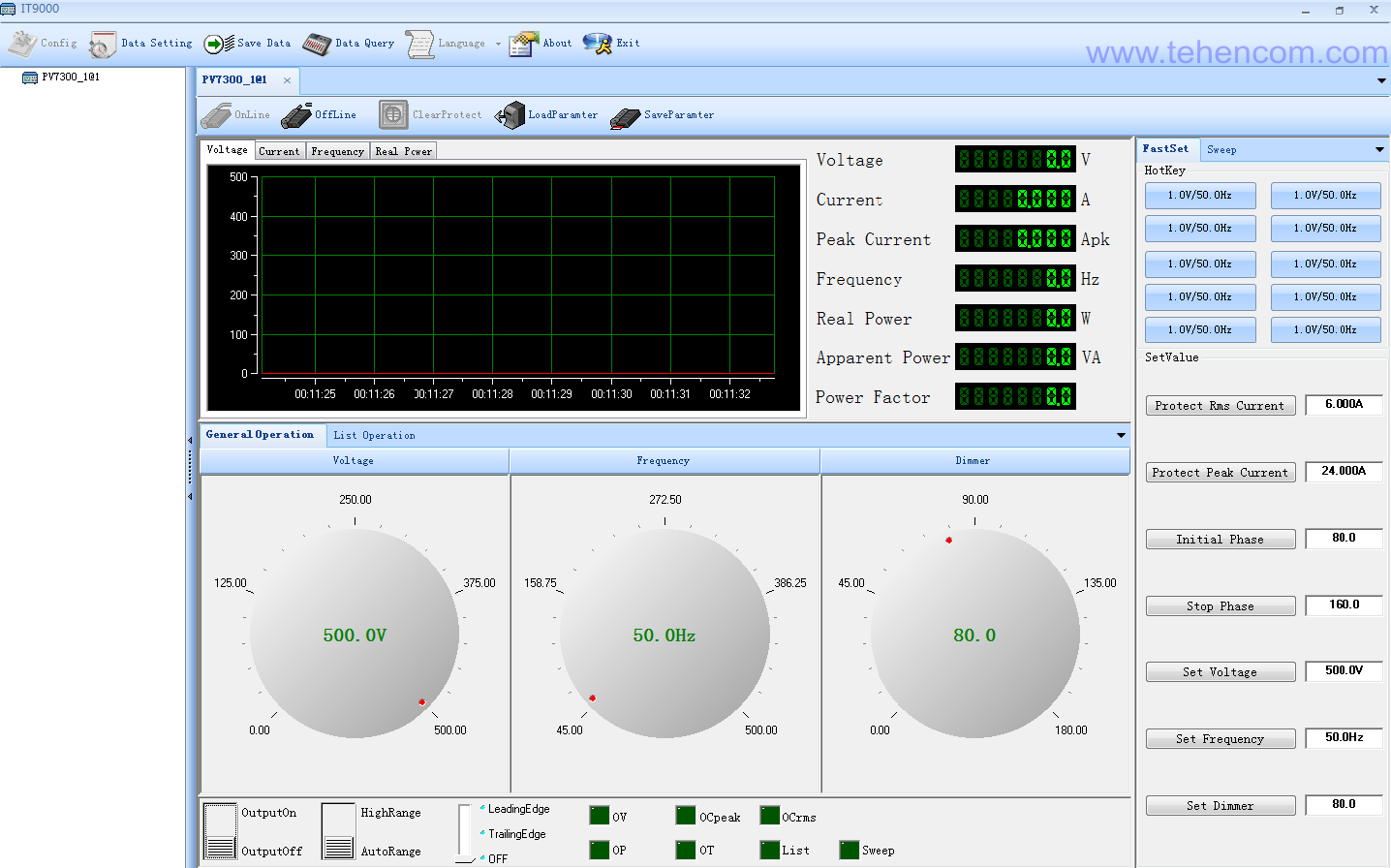
Usually, software control is used in two cases. The first is the use of a ready-made computer program that comes with the device. On the large screen of the computer, all the settings and parameters of the device are clearly visible, and this is very convenient. In addition, the power supply can be installed in the production room, and controlled remotely from your workplace. This can be useful if the production area is noisy, cold or very warm, contains hazardous conditions for humans, etc. If necessary, it is even possible to organize control of the device via fiber optics, which will exclude any electrical connection with the operator.
This figure shows a screenshot of the main window of the IT9000 program, which controls the operation of a laboratory AC voltage and current power supply of the series IT7300. All controls are located on one screen, as well as a detailed indication of the current status of the device.
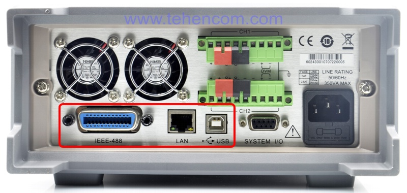
The second case when software control is used is the inclusion of laboratory power supplies in automated measuring systems. Previously, the IEEE-488.2 interface was most often used for this purpose (it is also called GPIB, and in GOST it was called Public Channel). But in recent years, Ethernet (LAN) and USB interfaces are actively gaining popularity in industrial automation systems, and outdated RS-232 and RS-485 interfaces are used less and less. In order to control the device, you will have to create your own programs. Control commands are described in detail in the programming manuals that are available for each series. An example of a programming guide for ITECH IT6500 series laboratory power supplies, see here. This photo shows the back panel of a modern power supply. ITECH IT6412, which is standardly equipped with three popular interfaces: IEEE-488.2, Ethernet (LAN) and USB.
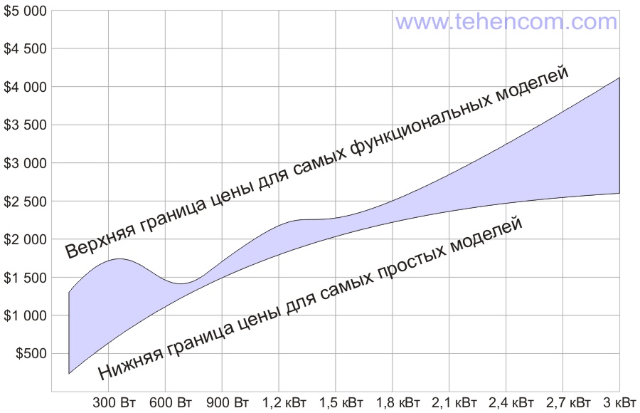
Price level, depending on the power of the model
The price of a laboratory power supply depends on the brand of the manufacturer, the maximum power output to the load, as well as a set of additional functions (overload protection, programmability, etc.). The figure below shows the price range of different LBP models depending on their maximum power. Please note that we only offer quality, reliable laboratory power supplies from manufacturers that are leaders in this field. Prices start at $250 for a 100 W model and can go up to several thousand dollars for 3 kW and higher models. You can quickly get accurate prices for the models you are interested in by sending us a request by E-mail.
Typical applications and popular models of laboratory power supplies
Now that we have dealt with the main criteria for choosing laboratory power supplies, let's look at typical tasks for using these devices and models of devices suitable for these tasks.
Universal laboratory power supply for a wide range of applications
For most typical tasks that arise when developing or repairing electronic equipment, the ITECH IT6900A series (up to 150 V, up to 25 A, up to 600 W), which was created as the main laboratory power supply capable of solving 90% of all issues, is excellent:
If you need a universal power supply, but for minimal money, then choose the ITECH IT6700 economy series. It has two models: 100 W and 180 W. There is no software control, but there is an automatic limitation of the output power, which is not often found in this price range:
High voltage and high current
If you need constant voltages of more than 100 V or currents of more than 10 A, feel free to choose one of the 15 models of the ITECH IT6700H series. Devices of this series can provide voltage up to 1 200 V and current up to 220 A with a maximum power of up to 3 kW. Both manual and software control is possible:
If you need a laboratory power supply to deliver more than 3 kW of power to the load, then the ITECH IT6000C series has no alternative. This is a new, highly functional series released at the end of 2018. The series consists of 69 models with voltage up to 2 250 V, current up to 2 040 A and power up to 144 kW:
Development and repair of precision analog equipment, audio circuits and sensitive sensors
For such tasks, linear laboratory power supplies are best suited. Consider the Keithley 2220 and Keithley 2230 series first. These are some of the best linear power supplies in terms of performance and price. In addition, with galvanic isolation of channels:
You can also look at this series of linear power supplies: Tektronix PWS4000.
AC voltage and current generation
If you need to generate a sinusoidal voltage or a sinusoidal current, then there are two series of sources with this capability. This is ITECH IT7300 series (1 phase, power up to 3 kVA):
And the powerful ITECH IT7600 series (1-phase and 3-phase, power up to 54 kVA):
Additional information on this topic
We deliberately did not overload this article with the technical details of the design of laboratory power supplies and a thorough description of their options. All this you can read in detail on individual model pages. And to deeply understand this issue and improve your professional level, study the documents on basic theory of the use of laboratory power supplies.
If you need detailed pricing information or technical advice on choosing the best power supply for your application, just call us or write to us at E-mail and we will be happy to answer your questions.
