ITU-T Y.1564 Test Method for Ethernet Service Activation: Description, Key Features and Benefits
Brief introduction
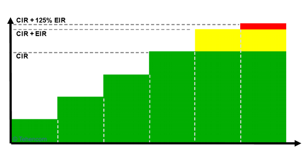
Recommendation ITU-T Y.1564 standardizes the measurement methodology required to verify the quality of services carried over Ethernet. As a result of the measurements performed by this technique, for each service it is possible to determine: the guaranteed data rate (CIR), the allowed exceedance of the guaranteed rate (EIR), packet delay (FTD), packet jitter (FDV), packet loss ratio (FLR) and a number of other important parameters.
Recommendation ITU-T Y.1564 implies two stages of measurement: in the first stage, the traffic of each service is generated and tested separately from other services, and in the second stage, all services are generated and tested simultaneously. To obtain the most complete and reliable results, it is recommended to use two separate instruments. In this case, the measurements will be performed individually for each of the two directions of data transmission.
Prior to the development of ITU-T Y.1564, most Ethernet networks were tested using the RFC 2544 methodology published in 1999. But the RFC 2544 methodology was originally developed for laboratory testing of Ethernet switches and similar Layer 2 equipment of the OSI model, so RFC 2544 is not the optimal methodology for making measurements in today's networks. RFC 2544 does not provide a way to test packet jitter, which is important for real-time applications. In RFC 2544, there is no way to test multiple services at the same time. When conducting a throughput test according to the RFC 2544 methodology (Throughput), overload and equipment failure of a working network is possible.
Therefore, the ITU-T Y.1564 recommendation, which is the subject of this article, is currently the best measurement technique for real Ethernet networks. This technique allows you to test in detail and quickly each service provided to the client, as well as to check the simultaneous operation of all services over a long period of time.
Independent measurements in two directions
Recommendation ITU-T Y.1564 specifically emphasizes that modern data networks are generally asymmetric in terms of the speed of information transmitted to and received from the network. There can be many reasons for the asymmetry of Ethernet traffic: the asymmetry of intermediate interfaces (for example, xDSL), the provider's bandwidth allocation policy, router settings, etc.
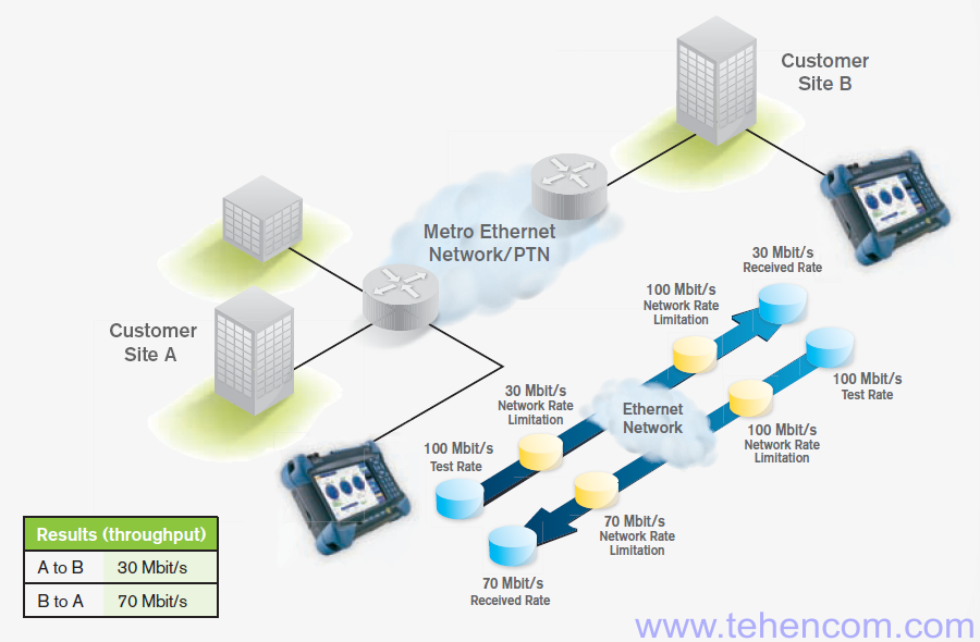
Therefore, in order to accurately identify sections and network elements that limit the transmission rate or are a source of errors, two separate measuring instruments must be used connected at different points of the tested network.
The figure below shows an example of an ITU-T Y.1564 measurement using two instruments. Both instruments are connected to the network via a physical 100 Mbit/s Ethernet interface. At the same time, there are two rate-limiting sections on the data path: 30 Mbps in the direction from A to B and 70 Mbps in the direction from B to A. It is obvious that the use of two devices allows you to get more information about the actual network performance and more pinpoint the source of the problem.
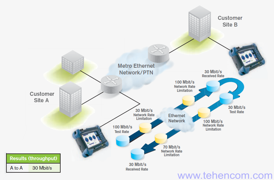
For special cases, the ITU-T Y.1564 recommendation allows measurement with a single instrument. In this case, packets at the far end of the network under test should be wrapped using a router or a second device in packet reflector mode. It is possible to carry out measurements according to this scheme, but not recommended for two reasons: firstly, the measurement results (speeds, delays, packet loss, etc.) in both directions will be combined into one digit and you will not be able to determine which direction the problem is in, secondly, all the limitations and delays of the device that performs packet wrapping will be added to the measurement results and cannot be separated.
The figure below shows an example of an ITU-T Y.1564 measurement using one instrument in conjunction with a packet reflector at the far end of the analyzed network section. The device is connected via a physical Ethernet interface 100 Mbps. As in the previous example, there are two rate-limiting sections on the data path: 30 Mbps in the direction from A to B and 70 Mbps in the direction from B to A. But as a result of such a measurement, we will get a figure of 30 Mbps and we will not be able to say in which of the directions this restriction arises. It is obvious that the use of a single device does not give a complete picture of the actual performance of the network and does not allow you to accurately determine the sources of problems.
Stage 1. The procedure for checking each service separately according to the ITU-T Y.1564 methodology
In modern networks, the traffic sent and received by the subscriber at the point of connection to the operator, as a rule, contains several data streams that are formed independently of each other by different devices and programs of the subscriber. If we consider, for example, an office center to which the operator provides 10 Gbps via dedicated fiber, then the traffic of such a subscriber will consist of many separate data streams, each of which provides a specific service (data transmission, voice communication, video viewing, etc.).
Some types of services are very sensitive to the loss or delay of packets, as well as to the unevenness of their arrival at the recipient (packet jitter). Services of this type include: video communication, voice communication, online games and other similar real-time applications. On the other hand, there are many services that are not very sensitive to delays or packet loss. These include: downloading files via the Internet, browsing websites, certain types of database queries, etc.
It is clear that for stable and correct operation of all office center equipment from our example through a fixed 10 Gb channel, it is necessary to correctly configure restrictions and priorities for different types of traffic. Such a setting, as a rule, is performed by the operator himself in order to provide the subscriber with a predetermined level of service, which is called SLA (Service Level Agreement) in English-language documents. VLANs and other similar methods can be used for this.
The ITU-T Y.1564 methodology was specifically designed to enable operators (providers) to measure the key indicators of the service they provide, simulating the real network load simultaneously with several traffic flows of different types. Measurements according to the ITU-T Y.1564 method are usually carried out at the points of connection of subscribers to the operator or at the points of connection of operators to each other.
At the first stage of measurements, which in the methodology of ITU-T Y.1564 is called the Service Configuration Test, each service is checked separately from other services. This is necessary in order to make sure that the network equipment is configured correctly, the ability to transmit this service at maximum speed and the ability to limit the speed of the service when it exceeds the specified value (Traffic Policing). The number and type of each service (independent data stream) is selected by the user in the meter menu before starting the test. Since the ITU-T Y.1564 methodology does not specify requirements for the number of services or their type, instrument manufacturers include in their products those capabilities that they believe are actually needed in practice.
A good device, as a rule, supports the simultaneous generation of up to 10 services. The Ethernet frame format can be set individually for each service: Ethernet II, 802.3 SNAP, etc. The Ethernet frame size may be fixed, or a sequence of frames of different lengths (EMIX) may be formed. An Ethernet frame can contain VLAN tags: C-VLAN, S-VLAN, E-VLAN, etc. Additionally, you can include a network layer protocol in an Ethernet frame: IPv4, IPv6, etc. You can also add transport layer protocols: UDP, TCP, etc. The type of each service can be set as data, voice (VoIP G.711, G.723.1, etc.) or video (MPEG-2, MPEG-4, etc.). All this functionality helps with the device to form such a data stream,
This figure shows the sequence of actions that the measuring instrument performs during the testing of one service according to the ITU-T Y.1564 methodology. See below for a detailed description of each step.
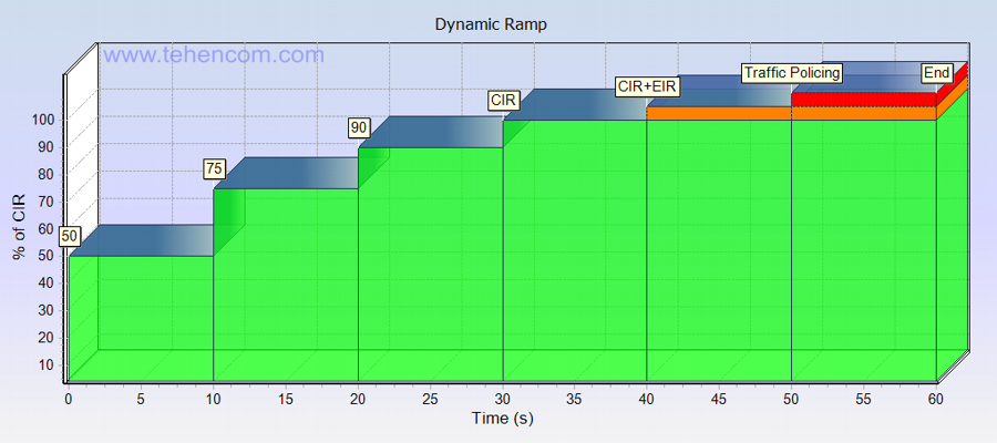
Step 1: within 10 seconds, form the data stream of Service 1 at a speed equal to 50% CIR (Committed Information Rate - guaranteed data transfer rate). At the same time, the second device on the receiving side measures the parameters of the received Service 1 stream: the actual reception rate, the FTD (Frame Transfer Delay) packet delay, the FDV packet jitter (Frame Delay Variation) and the FLR packet loss ratio (Frame Loss Ratio). All measured parameters must be within the specified limits, that is, comply with the SLA (Service Level Agreement).
Step 2: within 10 seconds, form the data stream of Service 1 at a speed equal to 75% CIR. The second device on the receiving side measures the parameters of the received stream. All measured parameters (speed, FTD, FDV and FLR) must meet the SLA.
Step 3: within 10 seconds, form the data stream of Service 1 at a speed equal to 90% CIR. The second device on the receiving side measures the parameters of the received stream. All measured parameters (speed, FTD, FDV and FLR) must meet the SLA.
Step 4: within 10 seconds, form the data stream of Service 1 at a speed equal to 100% CIR. The second device on the receiving side measures the parameters of the received stream. All measured parameters (speed, FTD, FDV and FLR) must meet the SLA.
Step 5: within 10 seconds, form the data stream of Service 1 at a speed equal to CIR + EIR (Excess Information Rate - exceeding the guaranteed data transfer rate). At the same time, the second device on the receiving side measures the actual rate of reception of the received stream. FTD, FDV, and FLR are measured, but they are not tested against specified limits, as latency and packet jitter are not guaranteed at CIR + EIR.
Step 6: within 10 seconds, form the data stream of Service 1 at a speed equal to CIR + 125% EIR. The second device on the receiving side measures the actual reception rate of the received stream, which, with properly configured Traffic Policing, should be greater than or equal to CIR, but less than or equal to CIR + EIR. The parameters FTD, FDV and FLR are measured, but their compliance with the specified limits is not checked.
The ITU-T Y.1564 methodology recommends setting the duration of each step in the range from 1 to 60 seconds and allows you to choose a different step of approaching the CIR. The figure above shows typical CIR approximations (50%, 75%, and 90%), as well as an optimal single step duration of 10 seconds.
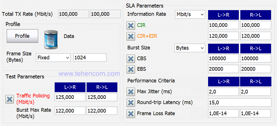
For a better understanding of how this works, the figure below shows a screen shot of the measuring instrument with the basic settings required to test one service according to the ITU-T Y.1564 methodology. If several services are checked, and there are at least three of them in a typical test, then similar settings must be made for each of them. Additionally, in a separate menu of the device for each service, you must select the Ethernet frame format and size, VLAN tags, network and transport layer protocols, etc.
Now a few comments on this screenshot. The designations L->R and R->L define the direction of testing: L->R stands for Local -> Remote (Near to Far) and vice versa. The Burst Max Rate and Burst Size (CBS and EBS) parameters are related to the optional Burst Burst Test, which is described below. The Max Jitter, Latency and Frame Loss Rate parameters set the level of guaranteed performance, they are taken from the SLA (Service Level Agreement) and must be provided by the tested network for each service transmitted at a rate less than or equal to CIR.
Burst Test
ITU-T Recommendation Y.1564 considers this test to be under development and not mandatory. But, at the same time, the usefulness of this test is emphasized, since it allows you to load and test the buffers of network devices, as well as the correctness of their work during bursts of traffic. The packet burst test is performed for each service separately and follows immediately after checking the service at CIR, EIR and Traffic Policing speeds.
There is an important note in ITU-T Y.1564: "Note that burst testing is most meaningful for high bandwidth Ethernet user network interfaces that have a small fraction of the line capacity provisioned to carry customer traffic. As the EIR or CIR grow to approach full line rate, the usefulness of burst testing declines, and it can take significantly longer to perform a burst test according to these procedures. These burst test procedures are designed to work best at committed and excess information rates up to 67% of maximum attainable information rate".
Translation of this remark: "Note that burst testing is most relevant for high-speed Ethernet interfaces where only a small fraction of the available bandwidth is used to carry user traffic. As the EIR or CIR grows to full interface speed, the usefulness of this test decreases and the time it takes to complete these procedures increases substantially. These burst test procedures are designed to work well at CIR and EIR rates not exceeding 67% of the maximum achievable bit rate.".
In fact, this test boils down to loading the network with a stream of packets of the selected service, transmitted at a rate greater than CIR (for the CBS test) or greater than CIR + EIR (for the EBS test), and then transmit packets at a rate equal to CIR (for CBS test) or equal to CIR + EIR (for EBS test). The exact burst rate (Burst Max Rate) is set by the user. Also, the user can set the total number of bytes transmitted during the CBS test and separately the total number of bytes transmitted during the EBS test. The CBS test means Committed Burst Size, that is, the guaranteed burst size. The EBS test means Excess Burst Size, that is, the excess of the guaranteed burst size. Both tests load the buffers of network devices with two different types of load.
This figure is a graphical representation of the sequence of actions for the CBS and EBS tests. Initially, the device maintains a pause during which no data is transmitted. Then it starts to transmit a burst of Ethernet frames with a minimum inter-frame interval. The burst speed and the number of bytes in it are set by the user. In the CBS test, after burst transmission, the device pauses again, and then follows a stream of Ethernet frames at the CIR rate. In the EBS test, the burst is immediately followed by a stream of Ethernet frames at CIR rate and immediately followed by a stream of frames at CIR + EIR rate. The user can set the percentage of the first and second pauses, as well as the ratio of the number of frames in the burst to the number of frames in the main stream.
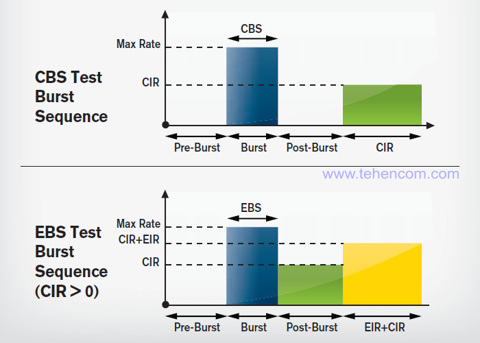
When performing a CBS type test, the measured parameters FTD (delay), FDV (jitter) and FLR (packet loss ratio) must comply with the SLA. And when performing a test like EBS, the parameters FTD, FDV and FLR are simply measured, but their compliance with the specified limits is not checked.
Stage 2. Procedure for checking all services together according to the ITU-T Y.1564 methodology
If, when checking each service separately according to the ITU-T Y.1564 method, no configuration errors of the network under test were found and all key indicators of the transmitted traffic of the services were within the specified limits, then you can proceed to the second stage of testing, namely, checking the simultaneous operation of all services at the rate of their guaranteed transmission CIR (Committed Information Rate). This test is called the Service Performance Test. It is simple in execution, but time consuming.
Simple in execution because all the necessary settings for each service were set before running the previous tests. Long in time because the purpose of this test is to test the ability of the network to transmit all services simultaneously, at the maximum guaranteed speed and for a long time. Therefore, the ITU-T Y.1564 methodology specifies three standard measurement periods: 15 minutes, 2 hours and 24 hours.
The measurement time of 15 minutes is recommended when connecting a new subscriber to an already operating operator's network. A measurement time of 2 hours is recommended for testing backbone connections between cities in a single operator's network. A measurement time of 24 hours is recommended for testing connections involving networks of several operators, as well as for international connections. In addition to the three standard periods, if necessary, the ITU-T Y.1564 methodology allows you to set a different measurement time.
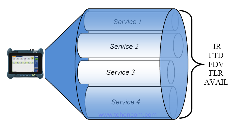
This figure shows a test run while generating four different services at the same time. Each service is transmitted at its individual guaranteed CIR rate. A second instrument at the far end of the network continuously measures all key metrics for each service and compares them to predetermined performance criteria, which are typically taken from the SLA.
The measured key indicators include five parameters: IR (Information Rate - information transfer rate), FTD (Frame Transfer Delay - frame (packet) transmission delay), FDV (Frame Delay Variation - frame delay variation (packet jitter)), FLR (Frame Loss Ratio - frame (packet) loss ratio and AVAIL (Availability - availability). For more information about the AVAIL parameter, which takes into account periods of loss of communication, see the text of the ITU-T Y.1564 recommendation.
Sequence of actions when testing a network according to the ITU-T Y.1564 methodology
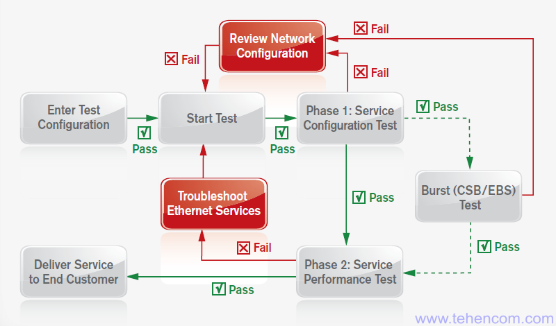
A typical sequence of actions for testing according to the ITU-T Y.1564 methodology is shown in the figure below.
First, you need to connect two measuring instruments at the points of the network between which the measurement will be carried out. Then, in the instrument menu, set how many and which services transmitted via Ethernet will be checked. For each service, you must select the Ethernet frame format and size, VLAN tags, network and transport layer protocols, and other parameters. For each service, you must specify a guaranteed data rate (CIR), an allowable overage of a guaranteed rate (EIR), packet delay (FTD), packet jitter (FDV), and packet loss ratio (FLR). If the network uses forced restriction of the rate of transmission of individual services (Traffic Policing), then you need to set the rate of this restriction. If the testing methodology involves burst testing, then for each service you need to set the CBS size, EBS size and burst rate. In the figure, all of the above is called "Enter Test Configuration".
After the test configuration is set, the first measurement phase (Phase 1: Service Configuration Test) is started. If during this measurement phase at least one of the services has an error, then it is necessary to check and correct the network hardware configuration (Review Network Configuration) and then repeat the "Service Configuration Test" again. If all services have been checked one by one and no errors have occurred, then you can proceed to the next step.
The next step is the Burst (CBS/EBS) Test. As already mentioned, this test is optional. If you decide to run it, then the result of this test should show that there are no network configuration errors. If an error occurs in at least one of the services during the Burst Test, then it is necessary to check and correct the network equipment configuration (Review Network Configuration), and then again perform the "Service Configuration Test" test and then again test with packet bursts. If no errors were found, then you can proceed to the next step.
The next step is the procedure for testing all the services together (Phase 2: Service Performance Test). During this test, all configured services are sent to the network at the same time. Each service is generated at its own guaranteed CIR rate. The test is carried out for a long time, usually it is either 15 minutes, or 2 hours, or 24 hours. If errors were found during the "Service Performance Test", then it is necessary to search for and eliminate their causes (Troubleshoot Ethernet Services) and, after elimination, start the entire measurement procedure from the very beginning. If no errors were detected and all measured key indicators met the established criteria, then you can draw up a measurement protocol and provide a service to the customer (Deliver Service to End Customer).
Recommended measuring instruments
To perform measurements according to the ITU-T Y.1564 methodology, appropriate measuring equipment is required. In this section, we present specific instrument models that can perform the required measurements and tests. As mentioned above, two devices are required for full operation.
List of recommended instruments and equipment:
- network analyzers 1G and 10G series EXFO MAX-800;
- measuring platform EXFO FTB-1 Pro with network analyzer module up to 10G series FTB-880v2;
- measuring platform EXFO FTB-1 Pro with network analyzer module up to 100G series FTB-890NGE;
- measuring platform EXFO FTB-2 Pro with network analyzer module up to 10G series FTBx-8880;
- measuring platform EXFO FTB-2 Pro with network analyzer module up to 100G series FTBx-88200NGE;
- checking the quality of optical connectors: EXFO FIP-400B.
This short video from EXFO explains how to test Ethernet according to ITU-T Y.1564. In EXFO analyzers, measurements using this technique are called EtherSAM.
Additional information on this topic
This page describes the main features of the ITU-T Y.1564 recommendation, which will allow you to appreciate the benefits of this technique and immediately start practical measurements. For those who want to delve deeper into the details, we recommend reading the original text of the original source in PDF format:
ITU-T Recommendation Y.1564 - full text of the standard (in English) (38 pages; 1 MB)
You may also be interested in this article:
40G, 100G, 200G and 400G Network Testing - Technology Description
To simplify the process of choosing an Ethernet / IP analyzer, you can use our experience and recommendations. We have over 20 years of practical supply experience and can immediately answer many questions about models, options, delivery times, prices and discounts. This will save your time and money. For this it's simple call us or write to us at E-mail and we will be happy to answer your questions.