Measuring the shielding effectiveness of materials up to 90 GHz
Brief introduction
To solve the problems of electromagnetic compatibility (EMC), resistance to electromagnetic interference (EMI), as well as technical protection of information (ITI), film shielding materials are widely used. There are many types of these materials: foils, paints, coatings, various types of fabrics, plastics containing metal powder, etc. This area of industry is actively developing and solid investments are coming into it.
Regardless of the type of shielding material, in the cycle of its development and production, there is necessarily a process of measuring the effectiveness of its shielding properties (shielding factor) in a certain frequency range. The measurement procedure itself is quite complicated and requires special equipment, as well as theoretical training and practical skills of engineering personnel.
This article provides basic information about the methods for measuring the effectiveness of shielding radio waves with film materials in the frequency range from 10 kHz to 90 GHz and the equipment necessary for this. Methods based on standards ASTM D4935, ASTM ES7, their extensions and modifications.
Theory and standards
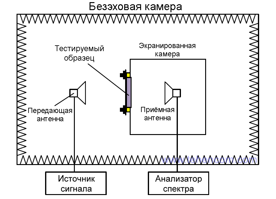
There are two approaches to measuring the shielding effectiveness of materials. The first method is based on the use of a shielded camera, inside which the receiving measuring antenna is located, aimed at the hole in the chamber wall, in which the test sample is fixed. The transmitting antenna is located outside the shielded chamber and is used to irradiate the sample with an electromagnetic signal. The entire set of equipment is located inside a large anechoic chamber, the task of which is to significantly weaken the re-reflection of radio signals inside the chamber and not let external electromagnetic interference into the chamber.
A simplified diagram of this method is shown in the figure below. It was standardized in 1956 by the military standard MIL-STD-285, which described a procedure for measuring the effectiveness of materials attenuating electromagnetic radiation in the frequency range from 100 kHz to 10 GHz. This method was further developed in the standard IEEE Std 299, which complemented and refined many aspects of measurements and extended the frequency range from 9 kHz to 18 GHz with the possibility of further extension from 50 Hz to 100 GHz.
The advantages of the measurement method according to MIL-STD-285 and IEEE Std 299 standards include: a wide frequency range and the ability to measure the shielding effectiveness of any solid materials, as well as powders and liquids (in appropriate containers). The main disadvantage of this method is that the cost of a complete set of equipment (including an anechoic chamber) can easily exceed $1,000,000.
The second standardized and widely used method measuring the shielding efficiency of materials is only suitable for thin samples (films, foils, coatings, fabrics, etc.), but it allows you to fully equip the laboratory for less than $100,000 and at the same time provides high accuracy. The essence of this method is to use vector network analyzer and compact TEM-cameras (Transversal ElectroMagnetic cell - transverse electromagnetic field cell). The procedure and the equipment used are described by two standards: ASTM ES7 and ASTM D4935.
The ASTM ES7-83 standard has become fundamental in the recognition of this method. It was adopted in 1983 and operated until 1988. TEM chambers conforming to this standard have a continuous conductor and the test piece must be round with a round hole in the center. Although formally the ASTM ES7 standard is no longer valid (withdrawn in 1988), today a large number of TEM camera models are produced according to this standard, allowing measurements in the range up to 3 GHz.
Later, in 1999, another standard was adopted: ASTM D4935-99, which was reissued in 2010 and 2018 and is currently valid. TEM chambers conforming to this standard have a cross section in which the test sample is fixed. In this case, the sample should be round or rectangular, depending on the cross-sectional shape of the TEM chamber used.
Despite several revisions of the ASTM D4935 document, it still standardizes a rather narrow frequency range: from 30 MHz to 1.5 GHz. This is due to the fact that in TEM-chambers having the design described in the standard, with increasing frequency, various parasitic effects (resonances, higher-order modes, etc.) begin to appear, which sharply reduce the measurement accuracy. However, thanks to the work of leading companies producing TEM cameras, as well as well-known scientific teams, it was possible to achieve an expansion of the frequency range up to tens of GHz by modifying the designs of TEM cameras.
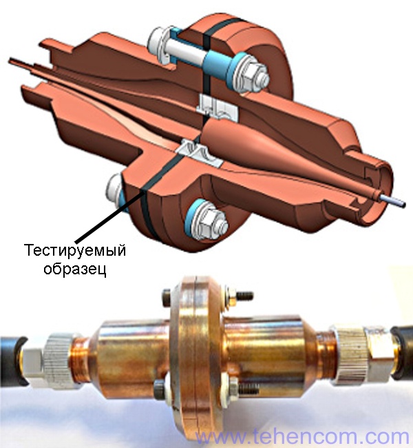
As an example, this figure shows a section and photograph of a TEM camera with a modified form that allows measurement of the shielding efficiency of a material sample in the frequency range from a few kilohertz to 3 GHz. A thin, flat, round specimen is placed between the two halves of the TEM chamber, which are then secured with three electrically insulated screws.
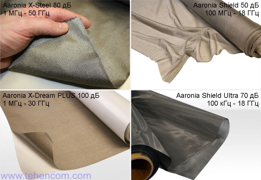
The photo below shows four materials (fabrics and film) produced by a German company Aaron especially for shielding rooms and equipment from electromagnetic interference. These materials are characterized by high shielding efficiency (up to 100 dB) and a wide frequency range (tens of gigahertz). The shielding efficiency of such materials is most easily measured using the methods and equipment described in this article: a vector analyzer and a set of TEM cameras.
Ready-made sets of equipment for different frequency ranges
In this section, we will look at several ready-made equipment kits that can be used to measure the shielding effectiveness of film materials in the frequency range from 10 kHz to 90 GHz.
First, main set equipment is based on a vector analyzer Anritsu MS46122A-020. This vector analyzer operates from 1 MHz to 20 GHz and provides over 100 dB of dynamic range. One or more TEM cameras are required to connect the sample under test. Since each TEM camera is limited to a certain frequency range, you choose models that completely cover the frequencies you need. Below are three different TEM cameras from the Japanese company KEYCOM.
| Name | Short description |
| S-152D-ES7 | TEM camera from 12 MHz to 800 MHz (ASTM ES7) |
| S-GPC7 | TEM camera from 500 MHz to 18 GHz (ASTM D4935, ASTM ES7), maximum specimen thickness 0.2 mm |
| S-39D-D4935 | TEM camera from 45 MHz to 3 GHz (ASTM D4935), maximum specimen thickness 0.2 mm |
| plus extra: | |
| DMP-11 | Software for vector analyzer control and material shielding efficiency calculation |
| GP-01 | GPIB cable for connecting the vector analyzer to a computer |
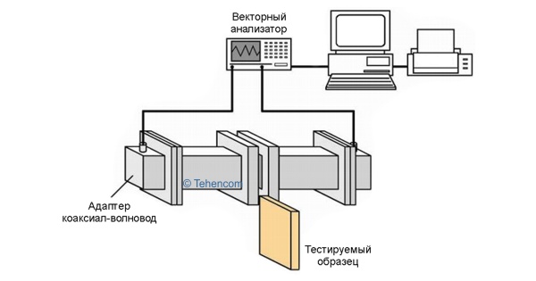
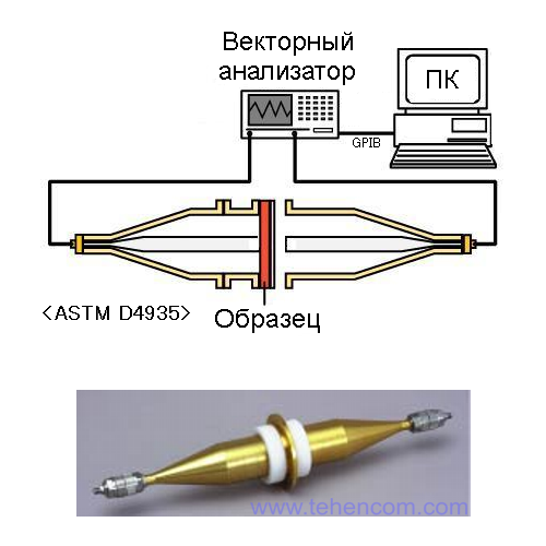
A block diagram of the connection to the vector analyzer and a photograph of one of the TEM cameras are shown in this figure. The round test specimen is clamped between the two halves of the TEM chamber.
Second set The equipment is designed for measurements starting from 10 kHz. It is based on a vector analyzer Anritsu MS2026C (if the upper frequency of 6 GHz is sufficient for you), or on the model Anritsu MS2028C (if it is necessary to measure up to 18 GHz). Just like in the previous kit, one or more TEM cameras, manufactured by the Japanese company KEYCOM, from the table below, must be added to the vector analyzer.
| Name | Short description |
| S-39D-ES7 Add-on | TEM camera from 10 kHz to 3 GHz (ASTM ES7) |
| S-152D-ES7 | TEM camera from 12 MHz to 800 MHz (ASTM ES7) |
| S-GPC7 | TEM camera from 500 MHz to 18 GHz (ASTM D4935, ASTM ES7), maximum specimen thickness 0.2 mm |
| S-39D-D4935 | TEM camera from 45 MHz to 3 GHz (ASTM D4935), maximum specimen thickness 0.2 mm |
| plus extra: | |
| DMP-11 | Software for vector analyzer control and material shielding efficiency calculation |
| GP-01 | GPIB cable for connecting the vector analyzer to a computer |
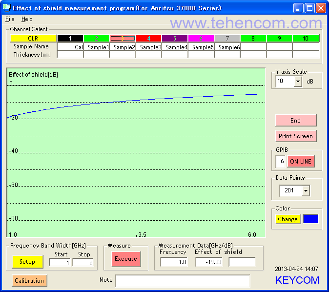
An important component of the measuring complexes offered above is the specialized DMP-11 software. A screenshot of the main window of this program is shown below. Its task is to control a vector network analyzer, read measurement results from it and recalculate these results using special formulas that take into account the parameters of the TEM camera used. The result of measuring the shielding effectiveness of the material is presented in the form of a graph and a table of values.
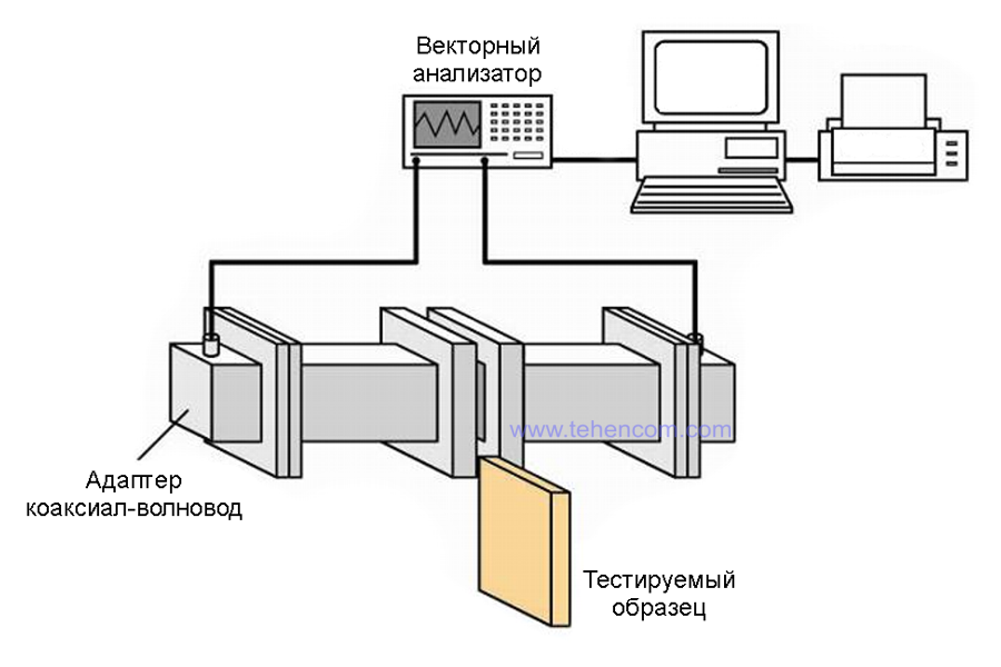
The two previous sets of equipment used circular TEM cameras. Third set The equipment we are going to review now uses rectangular TEM cameras and is designed to measure the shielding effectiveness of materials over a very wide frequency range, from 960 MHz to 90 GHz.
The block diagram of connecting the components of this kit is shown in the figure below.
Depending on the frequency range of interest, one or more of the twelve TEM cameras listed in the table below must be selected.
| Name | Short description |
| SEWR-770 | TEM camera from 960 MHz to 1.6 GHz (internal dimensions 195.6 by 97.8 mm.) |
| SEWR-430 | TEM camera from 1.6GHz to 2.6GHz (internal dimensions 109.2 by 54.6 mm.) |
| SEWR-284 | TEM camera from 2.6GHz to 3.95GHz (internal dimensions 72.1 by 34 mm.) |
| SEWR-187 | TEM camera from 3.95 GHz to 5.85 GHz (internal dimensions 47.6 by 22.1 mm.) |
| SEWR-159 | TEM camera from 4.9 GHz to 7.05 GHz (internal dimensions 40.4 by 20.2 mm.) |
| SEWR-137 | TEM camera from 5.85 GHz to 8.2 GHz (internal dimensions 34.9 by 15.8 mm.) |
| SEWR-90 | TEM camera from 8.2GHz to 12.4GHz (internal dimensions 22.9 by 10.2 mm.) |
| SEWR-62 | TEM camera from 12.4GHz to 18GHz (internal dimensions 15.8 by 7.9 mm.) |
| SEWR-42 | TEM camera from 18 GHz to 26.5 GHz (internal dimensions 10.7 by 4.3 mm.) |
| SEWR-28 | TEM camera from 26.5 GHz to 40 GHz (internal dimensions 7.1 by 3.6 mm.) |
| SEWR-19 | TEM camera from 40 GHz to 60 GHz (internal dimensions 4.8 by 2.3 mm.) |
| SEWR-12 | TEM camera from 60 GHz to 90 GHz (internal dimensions 3.1 by 1.6 mm.) |
| plus extra: | |
| DMP-12 | Software for vector analyzer control and material shielding efficiency calculation in the range from 1 GHz to 40 GHz |
| DMP-13 | Software for vector analyzer control and material shielding efficiency calculation from 40 GHz to 90 GHz |
| GP-01 | GPIB cable for connecting the vector analyzer to a computer |
At frequencies up to 40 GHz, it is necessary to use the DMP-12 software and a vector network analyzer of the appropriate frequency range from the series Anritsu MS46122A. At frequencies above 40 GHz, it is necessary to use the DMP-13 software and a vector network analyzer from the top series that is suitable for the frequency range Anritsu MS4640B VectorStar.
Additional information on this topic
In this article, we have proposed three ready-made sets of equipment for measuring the shielding efficiency of film materials in a very wide frequency range (from 10 kHz to 90 GHz). The proposed equipment and measurement methods are based on ASTM D4935, ASTM ES7, as well as their extensions and modifications.
Measurement of material parameters is an extensive and rather complex topic that requires special knowledge and skills from personnel. The set of equipment required for this directly depends on the type of material being tested, the frequency range of interest, and the parameters that need to be measured.
To save time on choosing the instruments and accessories you need, simply call us or write to us at E-mail and we will select the optimal set of equipment, as well as advise on the technical aspects of its application. In addition, we recommend that you familiarize yourself with the general theory vector analysis of electrical circuits and theory RF spectrum analysis.