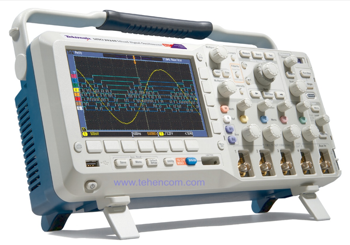
Tektronix MSO/DPO2000 200 MHz Mixed Signal Oscilloscope Series
Product code: 1000411
Add item to cart. Our specialist will coordinate with you the complete set, tell you the price and delivery time.
From 102 000 UAH
SHORT DESCRIPTION
Oscilloscope Series MSO/DPO2000 companies Tektronix (Tektronix) have a bandwidth of up to 200 MHz and a sampling rate of 1 GS/s, and also provide extensive functionality for debugging various types of devices, and all this at an affordable price!
With up to 20 channels for analyzing analog and digital signals, users can quickly find and identify problems in complex systems. To capture long waveforms while maintaining high time resolution, the MSO/DPO2000 Series oscilloscopes feature 1M record length per channel as standard.
Control Panel Wave Inspector provides fast waveform navigation and automated analysis of serial and parallel bus signals, making the MSO/DPO2000 Series oscilloscopes a full-featured tool for fast and easy debugging of complex systems. You can download a full description of all the characteristics below on this page in the section Documentation.
Areas of use:
- Embedded systems development and debugging
- Serial interface
debugging - Mixed-signal (MSO) debugging
- Automotive electronics development
- Power measurements
- Training
Tektronix MSO/DPO2000 Series Key Features:
100 MHz, 1 GS/s, 2 channels + 16 digital channels (Tektronix MSO2012 model).
100 MHz, 1 GS/s, 4 channels + 16 digital channels (Tektronix MSO2014 model).
200 MHz, 1 GS/s, 4 channels + 16 digital channels (Tektronix MSO2024 model).
100 MHz, 1 GS/s, 2 channels (Tektronix DPO2012 model).
100 MHz, 1 GS/s, 4 channels (Tektronix DPO2014 model).
200 MHz, 1 GS/s, 4 channels (Tektronix DPO2024 model).
Record length: 1 million points to the channel. Vertical resolution: 8 bit.
Sensitivity: 2 mV/div to 5 V/div with a calibrated setting.
Continuous waveform capture rate: up to 5,000 waveforms/s.
29 automatic measurements, FFT analysis (FFT), mathematical signal processing, cursor measurements, mask measurement, context help, Russian interface.
Interfaces: USB standard, Ethernet and VGA optional. Weight: 3.7 kg.
Advanced A/D debugging capabilities
Need an oscilloscope faster and cheaper? Watch the series Tektronix TBS2000.
Need USB oscilloscope up to 200 MHz? Watch the series PicoScope 3000D.
Need to measure conventional signals and radio signals? Watch the series Tektronix MDO3.
Need more analogue and digital channels? Watch the series Tektronix MSO5.
Need galvanized isolated channels? See Tektronix TPS2000B or Tektronix THS3000.
Difficult to decide on a model? See helper: How to quickly choose an oscilloscope.
All series of modern oscilloscopes are presented here:
Digital oscilloscopes and probes.
DETAILED DESCRIPTION
The MSO/DPO2000 Series oscilloscopes (models: MSO2012, MSO2014, MSO2024, DPO2012, DPO2014, DPO2024) are equipped with a wide range of features to speed up all stages of debugging - from fast anomaly detection and capture to event search and analysis of recorded waveforms and device behavior.
Detection and capture
In order to fix a problem, you first need to know that it exists. Each design engineer has to spend a lot of time troubleshooting the device under development, which, in the absence of suitable debugging tools, turns into a very tedious and time-consuming process.
The MSO/DPO2000 Series oscilloscopes offer a complete set of waveform visualization tools, allowing you to gain insight into the nature of your device faster and deeper. A waveform capture rate of 5,000 waveforms per second allows you to observe glitches and other rare transients, which helps to determine the true causes of device failures. The display with a digital phosphor with brightness gradation makes it possible to display the dynamics of signal changes, since the areas of the waveform where the signal appears more often have a higher brightness, which makes it possible to visually assess the frequency of anomalies.
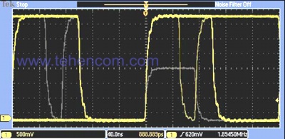
Detection - 5,000 waveforms per second acquisition rate maximizes the chance of detecting transient glitches and other infrequent events |

Capture - Trigger on a specific data packet transmitted over the RS-232 bus. Full set of triggering features, including triggering on the contents of a serial data packet, ensures that the event of interest is quickly captured |
Finding device faults is just the first step. Now you need to capture the event of interest so that you can determine the cause of its occurrence.
To do this, the MSO/DPO2000 Series oscilloscopes offer a complete set of triggers, including runt, logic, pulse width/glitch, setup/hold violation, serial bursts, and parallel data, to help you quickly locate the event of interest. With a record length of up to 1 million points, many events can be recorded in one capture, up to several thousand consecutive data packets. At the same time, high resolution is maintained, allowing you to see in detail the smallest details of the signal.
The MSO/DPO2000 Series oscilloscopes offer a wide range of capabilities, from triggering on specific data packet content to automatic decoding of various data formats. At the same time, they provide support for a wide range of serial buses: I2C, SPI, CAN, LIN and RS-232/422/485/UART. The ability to simultaneously decode up to two serial and/or parallel buses allows you to quickly identify problems at the system level.
Essential troubleshooting and signal analysis tools
Without the appropriate tools, finding an event of interest in a long signal record can be a very time consuming process. Given that modern instruments can record over a million points, searching for an event can mean scrolling through thousands of waveform screens.
The MSO/DPO2000 Series oscilloscopes offer the industry's most advanced search and navigation tools in an innovative control panel Wave Inspector. With these controls, you can speed up the process of panning and zooming parts of the record. Thanks to a unique system with a feedback mechanism, the user has the ability to move from one end of the record to the other in a matter of seconds. Using special custom labels, you can mark any area on the waveform, and then return to it for further study. In addition, the user has the ability to conduct an automatic search according to the criteria specified by him. The Wave Inspector instantly views the entire recording, including analog, digital, and serial bus data. At the same time, it automatically marks each moment of the occurrence of a given event. In the future, the user can quickly navigate between events using these labels.
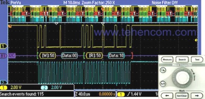
Search - Decodes I2C bus data and displays address 50 search results. Wave Inspector control panel provides unsurpassed efficiency in navigating and viewing data |
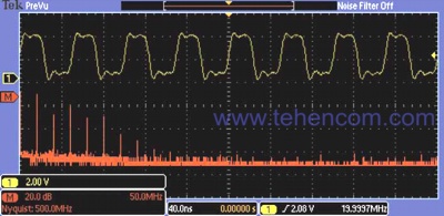
Analysis - Fast Fourier transform of impulse signals. Comprehensive suite of built-in analysis tools speeds up device design verification |
In order to check how the parameters of the prototype of the device being developed correspond to the model and whether they satisfy the goals set in the project, it is necessary to comprehensively analyze all the characteristics of the sample. This analysis can require a wide variety of measurements, from simple rise time and pulse width measurements to complex insertion loss (power loss) analysis and noise source analysis.
The MSO/DPO2000 Series oscilloscopes feature a complete set of built-in analysis tools, including waveform and screen-based cursors, 29 automatic measurements, and Fast Fourier Transform analysis. In addition, the instruments are equipped with specialized application programs for analyzing serial bus signals.
Navigation and search system Wave Inspector
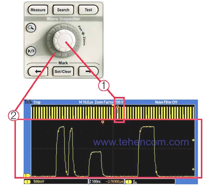
A record with a length of 1 million points represents thousands of screens of information. Thanks to the control panel Wave Inspector - the industry's best navigation and search tool - the MSO/DPO2000 Series oscilloscopes give you the ability to find the events you need in seconds. The Wave Inspector control panel provides unsurpassed efficiency in viewing, navigating and analyzing data. By turning the outer panning knob, you can quickly view the entire 1M-dot recording (1). Moving from start to finish will take a matter of seconds. Spotted something interesting and want to take a closer look? Just turn the internal zoom knob (2):
Wave Inspector includes the following innovative features:
Zoom/Pan (Zoom/Pan)
A dedicated two-level "Zoom/Pan" rotary knob on the front panel provides intuitive zoom and pan control. An internal "Zoom" knob allows you to adjust the stretch factor (or zoom). Turning it clockwise enables the signal to be stretched with a further gradual increase in the scaling factor. Turning the knob counterclockwise causes the stretch ratio to gradually decrease and eventually disables the zoom. Thus, it is no longer necessary to use multiple menus to adjust the image scale. Using the external Pan knob, you can move the view window around the waveform, which allows you to quickly get to the desired signal fragment. Besides, The outer knob is equipped with a feedback mechanism that allows you to control the panning speed of the waveform in proportion to the angle of rotation. The more you turn the outer knob, the faster the viewport moves. The panning direction is changed by simply turning the knob to the other side.
Play/Pause (Play/Pause)
A dedicated front-panel "Play/Pause" button allows you to automatically scroll through the waveform on the oscilloscope screen while searching for anomalies and other events of interest to the user. The playback speed and direction are controlled by the pan control. As with panning, increasing the angle of the knob moves the waveform faster, and turning the knob the other way changes the direction of scrolling.
Custom labels
To mark one or more points of interest on the waveform, press the "Set Mark" button on the front panel. Moving between labels is carried out using the adjacent buttons " " ("Forward").
Search marks
The "Search" button allows you to automatically browse long waveform records to search for user-defined events. All found events are marked on the oscillogram with search marks, between which you can easily navigate using the " " ("Forward") buttons. The following can be used as search criteria: front, pulse/glitch duration, degenerate pulse (runt), logical state, setup and hold time violation, rise/fall time of the signal edge in the parallel bus, as well as the contents of the I2C, SPI, CAN bus packets, LIN and RS-232/422/485/UART.

The first stage of the search: You indicate what you need to find |

The second stage of the search: Wave Inspector automatically scans the record and marks the found events. You can now move between events using the back and forward arrow buttons |
DPO digital phosphor technology
Used in MSO/DPO2000 series oscilloscopes digital phosphor technology allows you to quickly evaluate the functioning of the device under study. The 5,000 waveforms per second capture rate provides a high probability of detecting the rare but common failures in digital systems: runts, glitches, timing issues, and more.
The waveforms are superimposed on each other, with the points of the waveforms that appear more frequently being brighter. This allows you to quickly and clearly highlight events that occur relatively often, or, on the contrary, rarely occurring anomalies.
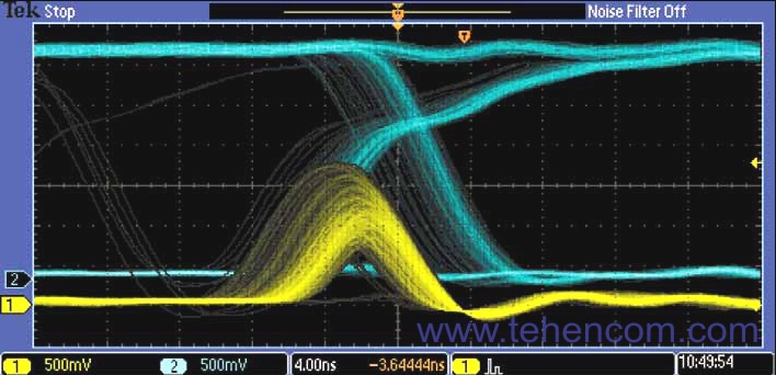
On the MSO/DPO2000 Series oscilloscopes, you can set the persistence to infinite or variable, which is the amount of time that previously captured waveforms remain on the screen. This allows you to determine how often this or that anomaly appears. Read more in a separate article: description of DPO technology.
Design and Analysis of Mixed Signal Devices (MSO Series)
The MSO2000 series mixed signal oscilloscopes have 16 digital channels. Their control is seamlessly integrated into the oscilloscope's user interface, simplifying operation and making it easy to solve problems that arise in devices that work with analog and digital signals.
Waveform color coding
The MSO2000 Series oscilloscopes provide a new way to visualize digital signals. All logic analyzers and mixed-signal oscilloscopes have one common drawback: the difficulty of determining the logical state of the signal - "0" or "1" - when choosing a sweep mode in which the digital waveform is a single solid horizontal line. The MSO2000 Series oscilloscopes color-code digital waveforms with logical ones in green and logical zeros in blue.
The MSO2000 Series oscilloscopes are equipped with multiple transition detection hardware that highlights the signal edge in white when a transition from one logical state to another is detected at a given point of uncertainty. The presence of a white edge is a signal that increasing the sample rate on the next capture may reveal high-frequency information that was not available at the previous settings.
The MSO2000 Series simplifies the channel setup process by allowing digital waveforms to be grouped and labeled using a USB keyboard. Signals can be combined into a group by simply placing them next to each other. When a group is formed, all channels in the group can be moved at the same time. This greatly reduces the setup time required to place each channel individually.
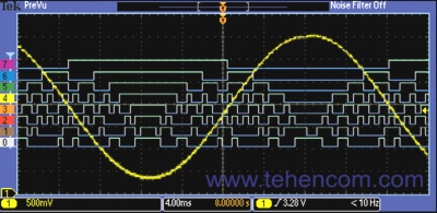
MSO Series oscilloscopes have 16 digital channels for viewing and analyzing time-related analog and digital signals |
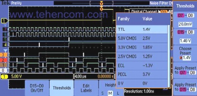
Color-coded digital waveform display allows you to group digital channels by simply placing them side by side on the screen |
P6316 Mixed Signal Oscilloscope Probe
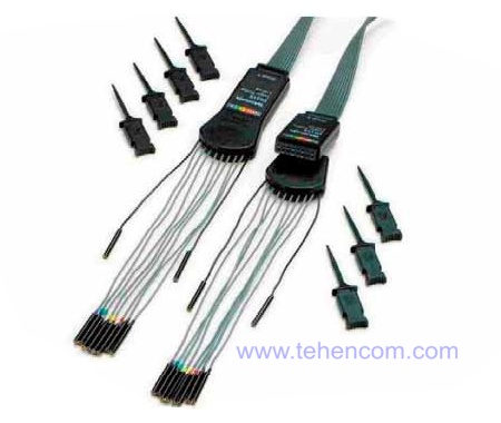
The unique design of this probe contains two groups of eight channels, making it easy to connect to your device under test. The P6316 probe can be directly connected to 16-pin (8*2) 2.54 mm pitch male headers located on printed circuit boards. In addition, if you need to connect to surface mount components or test points, you can use the supplied pigtail and clamp kit. The P6316 probe has excellent electrical performance with an input capacitance of only 8 pF and an input impedance of 101 kΩ.
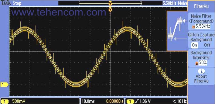
FilterVu™ Tunable Low Pass Filter
Lacking 20 MHz bandpass filter capabilities? Turn on FilterVu and set the tunable low pass filter for noise reduction. Unlike other tunable filters, FilterVu filters out unwanted noise while capturing glitches (short-term pulses) and other signal details across the entire oscilloscope bandwidth. To do this, two waveforms are displayed on the screen: a waveform that can be filtered (displayed in the foreground) and a waveform with glitches (background).
The filtered waveform uses a tunable low-pass filter to suppress noise, resulting in a clean signal image with clear edges and levels. This improves the accuracy of cursor measurements with the help and allows you to include clearer waveform images in your documentation. When the filter is set to the lowest cutoff frequency, no more than 1% of high-frequency components pass through it, which could cause noise on the waveform.
The glitch captured waveform shows the high frequency components of the signal in the full bandwidth of the oscilloscope. When using a peak detector, the oscilloscope can capture pulses as short as 5 ns, eliminating missing glitches and other high-frequency noise. FilterVu is ideal for capturing periodic, non-recurring and one-time events.
Serial triggering and analysis (optional)
Each signal transmitted over the serial bus contains a lot of information: address, control information, actual data, timing data, and so on. All this significantly complicates the selection of events of interest. The MSO/DPO2000 Series oscilloscopes offer a convenient set of serial bus debugging tools, including automatic triggering, decoding, and searching on I2C, SPI, CAN, LIN, and RS-232/422/485/UART bus signals.
Serial Trigger
Launch by the contents of the package, for example, by the beginning of the package, by given addresses, by certain data, by unique identifiers, etc.; while most popular serial interfaces are supported: I2C, SPI, CAN, LIN and RS-232/422/485/UART.
Bus display
Provides a high-level composite representation of the individual bus signals (clock, data, bus enable, etc.), making it easy to identify the start and end of packets and their components such as address, data, identifier, checksum, and others
Bus signal decoding
Tired of looking at waveforms, counting clock pulses and determining the value of each bit (0 or 1), and then concatenating those bits into bytes and calculating their hexadecimal values? Let the oscilloscope do it for you! After you set the bus type, the MSO/DPO2000 Series oscilloscopes will decode the contents of each packet and display its value on the bus waveform in hex, binary, decimal (LIN only), or text (RS-232/422/485/UART only). ) format.
Event table
In addition to displaying the decoded data packets directly on the bus waveform, all packets captured in the instrument's memory can be presented in a tabular form, approximately as they are reproduced in the program printout. Packets are timestamped and displayed sequentially, with each packet component (Address, Data, etc.) having a separate column.
Search
Serial triggering is very useful for highlighting events of interest. But if you have captured such an event and want to analyze it, what should you do next? Previously, in search of the cause of an event, the user had to manually scroll through the waveforms, read and convert bits. The MSO/DPO2000 Series oscilloscopes allow you to automatically view captured data and search by user-defined criteria, including the contents of serial data packets. Each detected event is marked with a search flag. To move quickly between labels, use the buttons " " ("Forward") located on the front panel.
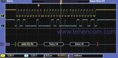
Trigger on a specific data packet transmitted over the I2C bus. The yellow waveform is the clock signal and the blue waveform is the data. The bus waveform shows the decoded contents of the packet, including Start, Address, Read/Write, Data, and Stop |
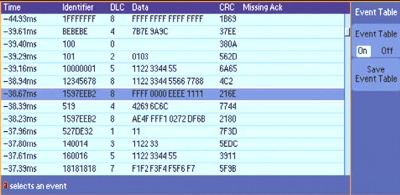
The event table displays the decoded content of each packet transmitted over the CAN bus: Identifier, Data Length Code (DLC), Data and Checksum (CRC) |
Advanced analysis tools
The MSO/DPO2000 Series oscilloscopes can display data and measurement results by simply connecting the oscilloscope to a computer with a USB cable. All Required Software - NI LabVIEW signalexpress™ Tektronix Edition LE, OpenChoice Desktop and Microsoft Excel and Word toolbars are standard and provide quick and easy interaction with a Windows PC.
NI LabVIEW SignalExpress Tektronix Edition LE software lets you instantly capture, generate, analyze, compare, import, and save measurements and waveforms with drag and drop, with no programming required. The professional version of the software (optional) includes more than 200 built-in functions for advanced signal processing, advanced analysis, sweeping, boundary testing, and user-defined stepping modes.
For simple tasks, the included OpenChoice Desktop software provides quick and easy communication between the oscilloscope and a computer via USB, GPIB, or LAN, and allows you to transfer settings, waveforms, and screenshots.

NI LabVIEW SignalExpress Tektronix Edition is a fully interactive acquisition measurement and analysis software optimized for MSO/DPO series oscilloscopes |

OpenChoice Desktop software makes it easy to connect your oscilloscope to your computer |
The MSO/DPO2000 is built for comfort
The MSO/DPO2000 Series oscilloscopes feature a 7-inch (180 mm) widescreen TFT LCD display that allows you to view the finest signal details. Controls for vertical deviation parameters for each channel provide simple and intuitive operation of the instrument. You no longer have to use the same set of controls for all four channels.
The USB port on the front panel allows you to save screenshots, instrument settings, and waveforms to USB storage devices. The rear panel has a USB port for remote control of the oscilloscope from a PC or for connecting a USB keyboard. The USB port can also be used for direct printing to a PictBridge compatible printer. An additional 10/100 Ethernet port provides a LAN connection, and an optional video output lets you display the oscilloscope screen on an external monitor or projector.
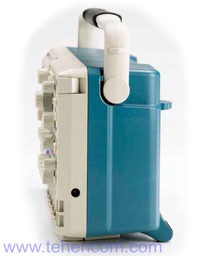
The MSO/DPO2000 Series oscilloscopes can be easily transported between laboratories due to their small size and weight. The instruments are only 134 mm deep, which saves usable space in the workplace.
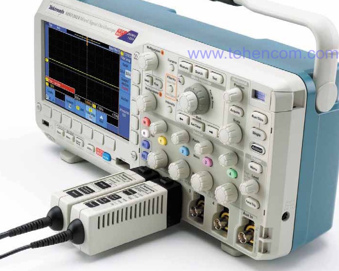
TekVPI® Probe Interface
The TekVPI probe connection interface greatly simplifies the work. TekVPI probes are equipped with status indicators and controls, as well as a probe menu button located directly on the compensator block. This button displays the probe menu on the oscilloscope screen with related settings and controls. TekVPI probes can be controlled remotely via USB, GPIB, or Ethernet interfaces, allowing for flexible solutions in automated test and measurement systems.
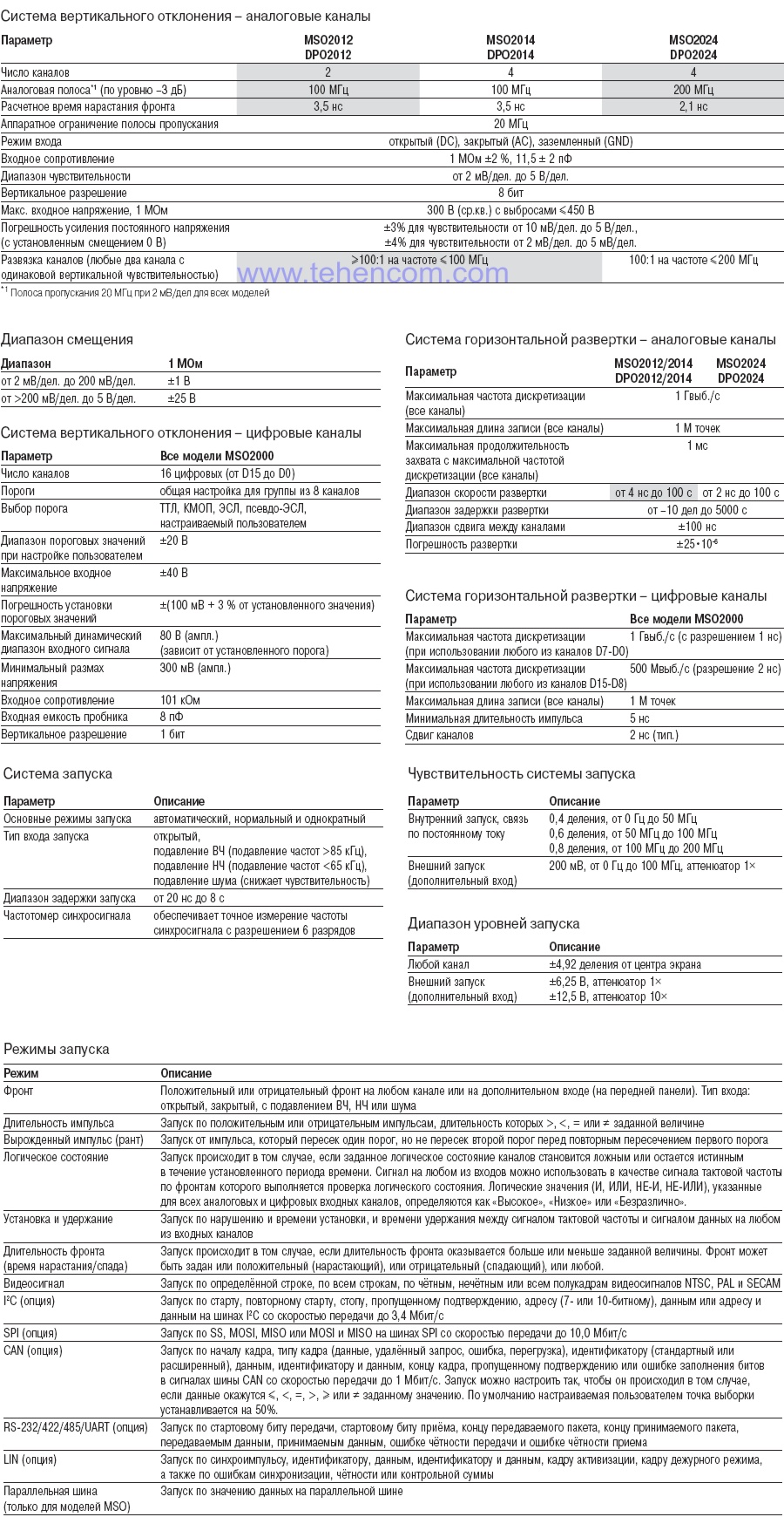
Tektronix MSO2000 and DPO2000 Series Oscilloscope Specifications
Tektronix MSO2000 and DPO2000 Series Oscilloscope Package Contents

Options and Accessories for Tektronix MSO2000 and DPO2000 Series Oscilloscopes

Documentation
This PDF documentation provides the most comprehensive description of the Tektronix MSO2000 and DPO2000 Series oscilloscope features, specifications, and modes of operation:
Description of the Tektronix MSO2000 and DPO2000 Series Mixed Signal Oscilloscopes (16 pages; 1.1 MB)
And here you can find our tips and other useful information on this topic:
How to quickly choose an oscilloscope - selection criteria, typical applications and popular models
DPO digital phosphor technology in oscilloscopes - principle of operation, application examples
Passive voltage probes for oscilloscopes
How to buy equipment cheaper - discounts, special prices, demo and used devices
To simplify the process of choosing a digital oscilloscope, you can use our experience and recommendations. We have over 20 years of practical supply experience and can immediately answer many questions about models, options, delivery times, prices and discounts. This will save your time and money. For this it's simple call us or write to us at Email and we will be happy to answer your questions.